Removal Procedure
- Raise and support the vehicle. Refer to JACKING AND LIFTING
in General Information.
- Remove the tire and wheel. Refer to TIRE AND WHEEL REMOVAL AND INSTALLATION
in Tires and Wheels.
- Unload the torsion bar. Refer to TORSION BAR REPLACEMENT
.
- Remove the wheel hub and bearing. Refer to WHEEL HUB, BEARING, AND SEAL REPLACEMENT (RWD)
or WHEEL HUB, BEARING, AND SEAL REPLACEMENT (AWD)
.
- Remove the outer tie rod cotter pin and retaining nut.
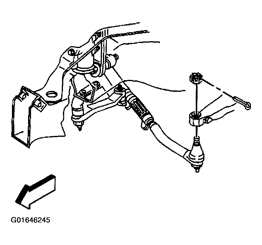 Courtesy of GENERAL MOTORS CORP.
- Remove the outer tie rod from the steering knuckle using J 24318-B.
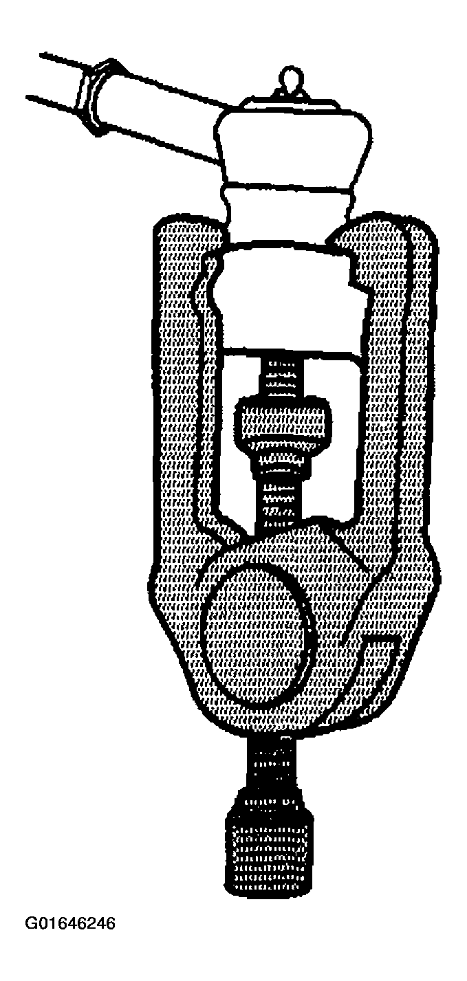 Courtesy of GENERAL MOTORS CORP.
- Remove the upper ball joint cotter pin and retaining nut.
- Install the J 366-7
to the upper ball joint and the steering knuckle.
- Disconnect the upper ball joint from the steering knuckle using the J 36607.
- Remove the lower ball joint cotter pin and retaining nut.
- Using a pry bar, placed on top of the upper control arm and on the bottom of the frame, pry downward.
- With the aid of a helper, carefully hammer on the steering knuckle in the area of the lower ball joint stud in order to release the stud from the steering knuckle.
- Place a pry bar on the top of the upper control arm and on the bottom of the frame, and pry downward.
- With the aid of an assistant, carefully hammer on the steering knuckle in the area of the lower ball joint stud in order to release the stud from the steering knuckle.
- Remove the steering knuckle.
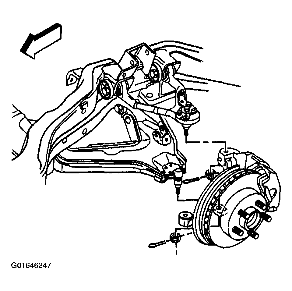 Courtesy of GENERAL MOTORS CORP.