Removal Procedure
- Remove the 2 screws that retain the insulator panel to the instrument panel (I/P).
- Release the insulator panel retaining clip from the I/P substrate.
- Lower the insulator panel.
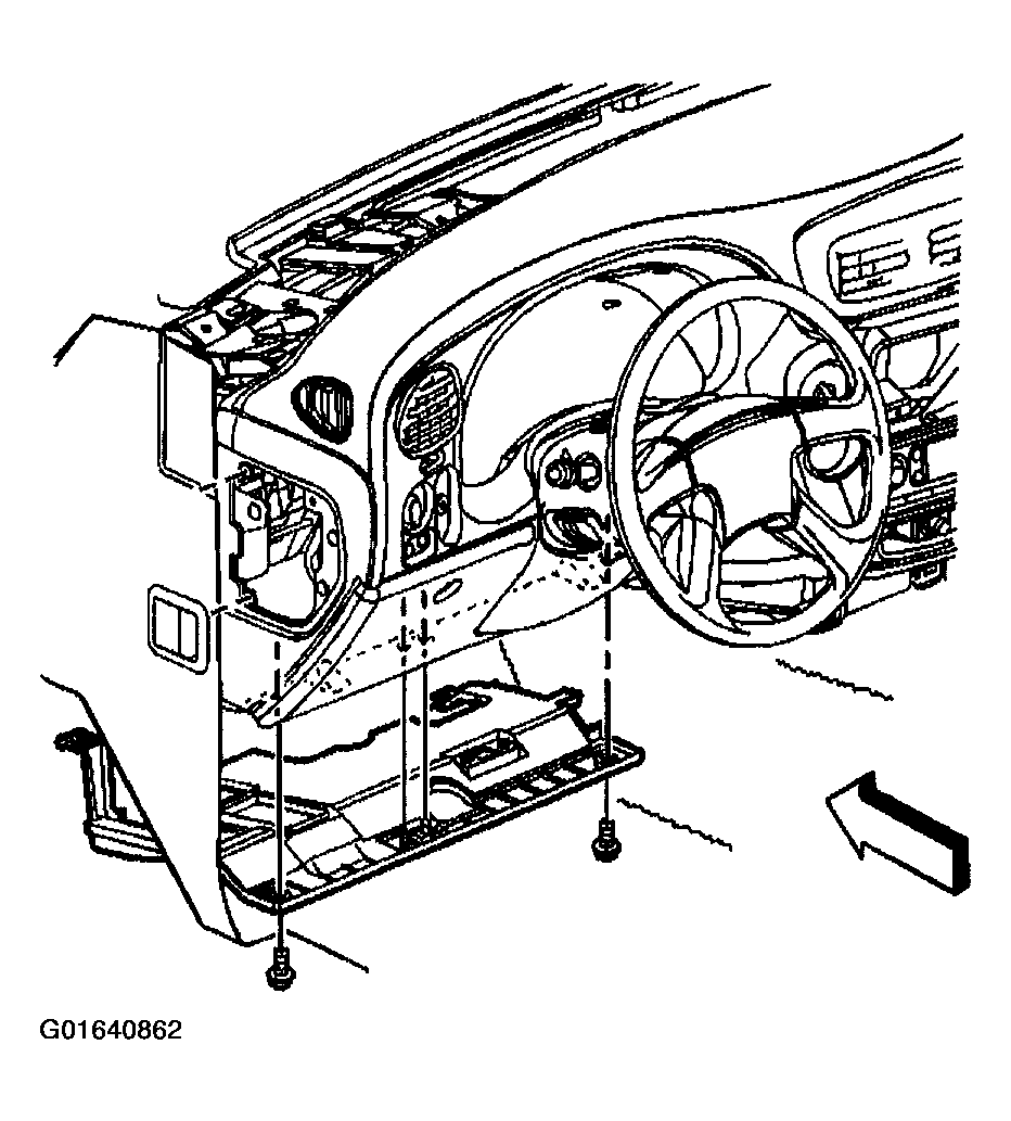 Courtesy of GENERAL MOTORS CORP.
- Remove the 2 data link connector (DLC) retaining screws.
- Remove the DLC from the insulator panel.
- Remove the splice pack from the insulator panel.
- Remove the hazard and turn signal flasher from the insulator panel. Refer to HAZARD AND TURN SIGNAL FLASHER REPLACEMENT
in Lighting Systems.
- Remove the insulator panel from the I/P.
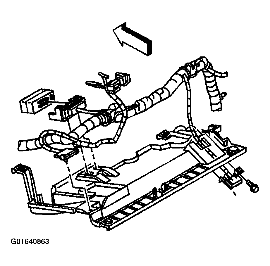 Courtesy of GENERAL MOTORS CORP.