Drive/Propeller Shaft: Service and Repair
Propeller Shaft Replacement - FrontRemoval Procedure
Important: The driveline components in this vehicle are factory system-balanced. System balance provides a smoother running driveline operation. Observe the position of all the driveline components. Accurately mark the relationship of the components before removal. These components include the propeller shafts, the drive axles, the pinion flanges, and the output shafts. All components must be reassembled in the exact relationship to each other as they were before removal. Follow the specifications, the torque values, and any measurements made prior to disassembly in order to maintain the factory system balance.
1. Raise the vehicle. Refer to Vehicle Lifting.
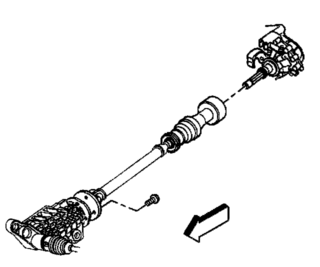
2. Accurately reference mark the propeller shaft to the front axle flange.
3. Remove the bolts from the propeller shaft to the front axle.
4. Remove the propeller shaft.
Installation Procedure
1. Install the rear of the propeller shaft to the transfer case.
2. Install the propeller shaft to the front axle. Line up the reference marks made previously.
Notice: Refer to Fastener Notice in Service Precautions.
3. Install the bolts to the front axle.
Tighten the bolts to 45 Nm (33 ft. lbs.).
4. Lower the vehicle. Propeller Shaft Replacement - Rear
Removal Procedure
Important: The driveline components in this vehicle are factory system -balanced. System balance provides a smoother running driveline operation. Observe the position of all the driveline, components. Accurately mark the relationship of the components before removal. These components include the propeller shafts, the drive axles, the pinion flanges, and the output shafts. All components must be reassembled in the exact relationship to each other as they were before removal. Follow the specifications, the torque values, and any measurements made prior to disassembly in order to maintain the factory system balance.
1. Raise the vehicle. Refer to Vehicle Lifting.
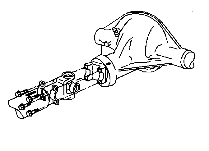
2. Accurately reference mark the propeller shaft.
3. Remove the bolts from the rear of the pinion flange.
4. Remove the retainers.
Important: Do not pound on the original propeller shaft yoke ears. The injection joints may fracture. Never pry or place any tool between a yoke and a universal joint.
5. Remove the yoke and cross assembly.
6. Tape the bearing cups in order to prevent the loss of bearing rollers.
7. Remove the propeller shaft by using the following procedure:
7.1. Slide the propeller shaft forward.
7.2. Lower the propeller shaft and remove under the rear axle.
7.3. Do not allow the universal joint to incline greatly; the joint may fracture.
8. Clean all the parts with a suitable solvent.
9. Inspect the outer diameter of the nylon injected yoke for burrs. Burring damages the transmission seal.
10. Inspect for proper installation and uniform seating of the bearing cups.
11. Inspect the slip yoke splines for wear.
12. Inspect for twisted slip yoke splines or possibly the wrong universal joint. Replace the parts as necessary.
Installation Procedure
1. Install the propeller shaft into the transmission.
Important: Install a new universal joint whenever a slip joint or companion flange is serviced.
2. Lubricate the slip joint.
3. Install the yoke and cross assembly onto the pinion flange.
4. Align the reference marks on the pinion flange and the propeller shaft rear yoke. Seat the yoke properly.
5. Install the retainers.
Notice: Refer to Fastener Notice in Service Precautions.
6. Install the bolts into the pinion flange.
Tighten the bolts to 36 Nm (27 ft. lbs.).
7. Lower the vehicle.