Side Bearings Replacement
Differential Side Bearings Replacement^ Tools Required
- J 22912-01 Bearing Puller
- J 25299 Differential Side Bearing Installer
- J 8092 Driver Handle
- J 8107-2 Differential Side Bearing Remover Plug
Removal Procedure
1. Remove the differential from the rear axle housing.
2. Remove the differential side bearings by doing the following:
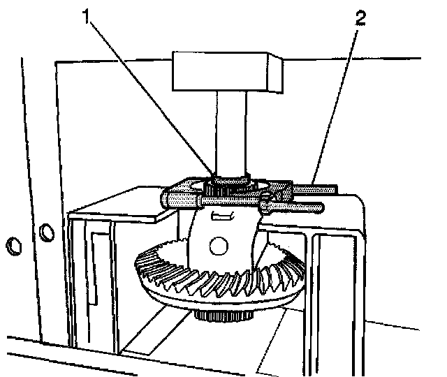
2.1. Install the J22912-01 (2) onto the differential case.
2.2. Install the J 8107-2 (1) onto the differential case bearing.
2.3. Remove the differential side bearings using the J22912-01 and a hydraulic press.
Installation Procedure
1. Install the differential side bearings by doing the following:
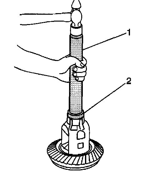
1.1. In order to protect the differential case, install the J 8107-2 (2) in the case on the side opposite the bearing installation.
1.2. Install the J 25299 (2) and the J 8092 (1) onto the differential case bearing as shown.
1.3. Drive the bearing onto the case using the J 25299 (2) and the J 8092 (1).
2. Install the differential.
Removal Procedure
Caution: To avoid any vehicle damage, serious personal injury or death when major components are removed from the vehicle and the vehicle is supported by a hoist, support the vehicle with jack stands at the opposite end from which the components are being removed.

Important: The driveline components in this vehicle are factory system-balanced. System balance provides a smoother running driveline operation. Observe the position of all the driveline components. Accurately mark the relationship of the components before removal. These components include the propeller shafts, the drive axles, the pinion flanges, and the output shafts. All components must be reassembled in the exact relationship to each other as they were before removal. Follow the specifications, the torque values, and any measurements made prior to disassembly in order to maintain the factory system balance.
1. Raise the vehicle. Refer to Vehicle Lifting.
2. Support the rear axle housing separately.
3. Remove the tires and wheels.
4. Remove the brake drums.
5. Disconnect the shock absorbers from the axle.
6. Make alignment marks on the propeller shaft and the pinion flange.
7. Disconnect the rear propeller shaft from the axle.
8. Secure the propeller shaft up and out of the way in a manner avoiding stress on the universal joints.
9. Disconnect the brake hose at the axle housing.
10. Disconnect the park brake cables.
11. Remove the U-bolts and anchor plates.
12. Remove the vent hose from the axle housing.
13. Lower the axle housing from the vehicle.
Installation Procedure
1. Raise the axle to the vehicle.
2. Install the vent hose to the axle housing.
3. Install the U-bolts and anchor plates.
4. Connect the rear brake hose to the rear brake pipe.
5. Connect the parking brake cables.
6. Install the brake drums.
7. Align the marks made on the propeller shaft with the marks made on the pinion flange/yoke.
8. Connect the rear propeller shaft to the axle.
9. Connect the shock absorbers to the axle.
10. Install the tires and wheels.
11. Add the axle lubricant to the axle housing. Use the proper fluid.
12. Lower the vehicle.
13. Bleed the brake system.