Diagnostic Procedure
- If audible warnings diagnostic system check has been performed, go to next step. If audible warnings diagnostic system check has not been performed, see AUDIBLE WARNINGS DIAGNOSTIC SYSTEM CHECK
under SELF-DIAGNOSTIC SYSTEM.
- Turn ignition switch to OFF position. Connect scan tool to Data Link Connector (DLC). Turn ignition switch to ON position. Using scan tool, observe KEY IN IGNITION parameter in Body Control Module (BCM) 1 Input data list. If KEY IN IGNITION parameter indicates YES, go to next step. If parameter does not indicate YES, go to step 4
.
- While observing KEY IN IGNITION parameter on scan tool, turn ignition switch to OFF position. If parameter displays ACTIVE when ignition switch is turned to OFF, go to step 7
. If operation is not as specified, go to step 11
.
- Turn ignition switch to OFF position. Disconnect BCM connector C2. Connect a test lamp between BCM connector C2 terminal B9 (Light Green wire) and ground. See Fig 1
. Place key in ignition. If test lamp illuminates, go to step 8
. If test lamp does not illuminate, go to next step.
- Check Light Green wire between ignition key alarm switch and BCM. See WIRING DIAGRAMS
. Check circuit for open or high resistance. Repair circuit as necessary, then go to step 12
. If no problem is found, go to next step.
- Check Tan wire between ignition key alarm circuit and connector C211 terminal B4. Check Black wire between connector C211 terminal B4 and ground. See Fig 2
. See WIRING DIAGRAMS
. Check wiring for open or high resistance. Repair circuit as necessary, then go to step 12
. If no problems are found, go to step 9
.
- Check Pink wire between IPC connector terminal A7 and fuse block GAUGES fuse (10-amp). See Fig 3
. See WIRING DIAGRAMS
. Check circuit for short to voltage. Repair wiring as necessary, then go to step 12
. If no problem is found, go to step 11
.
- Check BCM connectors for poor connection or corroded terminals. Repair connection as necessary, then go to step 12
. If no problem is found, go to step 11
.
- Check ignition switch connector for poor connections or corroded terminals. Repair connection as necessary, then go to step 12
. If no problem is found, go to next step.
- Replace ignition switch. See appropriate STEERING COLUMN SWITCHES article. When repair is complete, go to step 12
.
- Replace BCM. See appropriate BODY CONTROL MODULES article. When repair is complete, go to next step.
- Using scan tool, clear DTCs. Turn ignition switch to ON position and monitor for DTCs. If DTC B2961 resets, go to step 2
. If DTC does not reset, repair is complete.
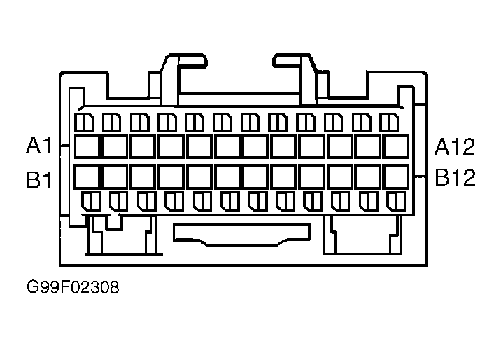 Courtesy of GENERAL MOTORS CORP.
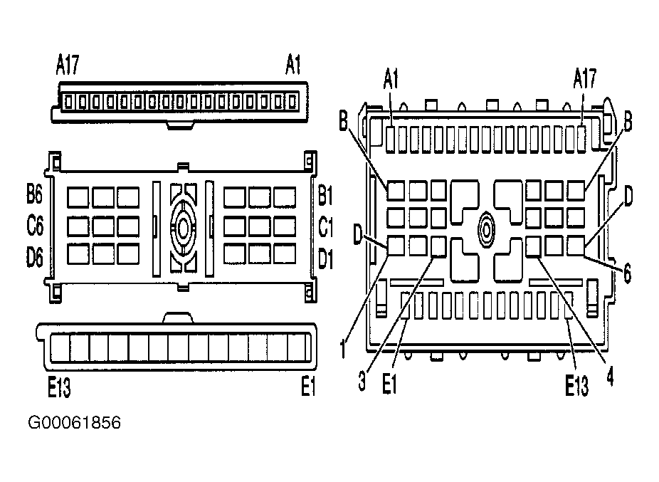 Courtesy of GENERAL MOTORS CORP.
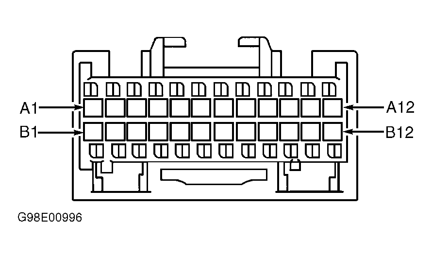 Courtesy of GENERAL MOTORS CORP.