Diagnostic Procedure
- If Instrument Panel Cluster (IPC) diagnostic system check has been performed, go to next step. If IPC diagnostic system check has not been performed, see INSTRUMENT PANEL CLUSTER DIAGNOSTIC SYSTEM CHECK
under SELF-DIAGNOSTIC SYSTEM.
- Turn ignition switch to OFF position. Connect scan tool to Data Link Connector (DLC). Using scan tool, observe FUEL TANK LEVEL REMAINING parameter in PCM data list. If parameter indicates less than one percent, go to next step. If parameter does not indicate less than one percent, system is functioning properly at this time. Check for intermittent fault. See DIAGNOSTIC AIDS
.
- Turn ignition switch to OFF position. Disconnect connector C104. Using scan tool, observe FUEL TANK LEVEL REMAINING parameter in PCM data list. If parameter indicates greater than 99 percent, go to step 5
. If parameter does not indicate greater than 99 percent, go to next step.
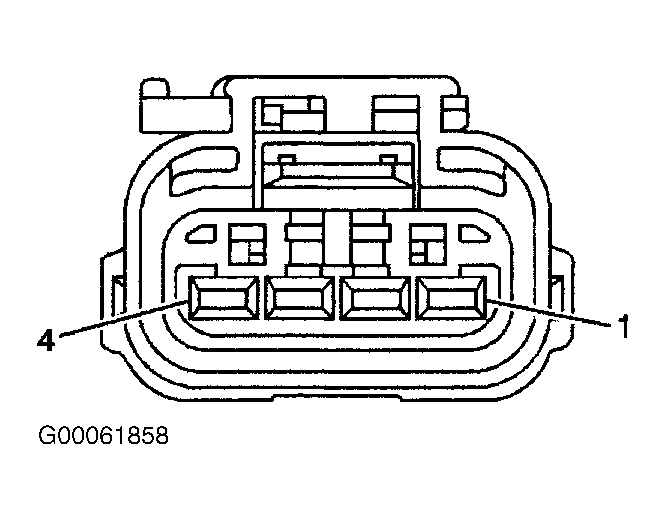
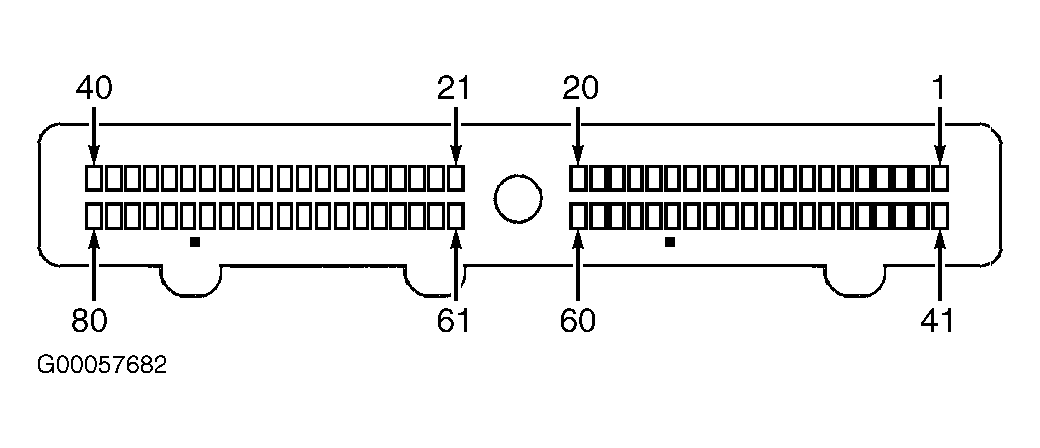
- Check signal circuit of fuel level sender between fuel sender unit and PCM. On 2.2L engines, check Purple wire between fuel level sender connector terminal No. 2 and PCM connector C1 terminal No. 55. See Fig 1
and Fig 2
. See WIRING DIAGRAMS
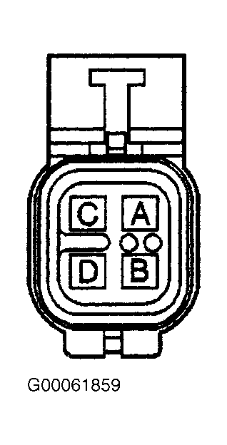
. On 4.3L engines, check Purple wire between fuel level sender connector terminal "A" and PCM connector C2 terminal No. 54. See Fig 2
andFig 3
. See WIRING DIAGRAMS
. On all models, check circuit for short to ground. Repair wiring as necessary, then go to step 10
. If no problem is found, go to step 7
.
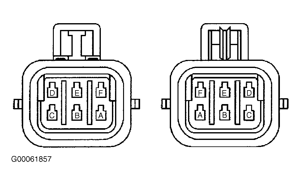
- Check Purple wire between connector C104 terminal "E" and fuel level sender connector terminal No. 2 (2.2L engines) or fuel level sender connector terminal "A" (4.3L engines). See Fig 1
,Fig 3
orFig 4
. See WIRING DIAGRAMS
. Check circuit for short to ground. Repair wiring as necessary, then go to step 10
. If no problem is found, go to next step.
- Check fuel level sender connector for poor connection or corroded terminals. Repair connection as necessary, then go to step 10
. If no problem is found, go to step 8
.
- Check PCM connector for poor connection or corroded terminals. Repair connection as necessary, then go to step 10
. If no problem is found, go to step 9
.
- Replace fuel level sender. See REMOVAL, OVERHAUL & INSTALLATION - TRUCKS article in ENGINE PERFORMANCE. When repair is complete, go to step 10
.
- Replace PCM. See REMOVAL, OVERHAUL & INSTALLATION - TRUCKS article in ENGINE PERFORMANCE. When repair is complete, go to next step.
- Using scan tool, clear DTCs. Turn ignition switch to ON position, then monitor for PCM DTCs. If DTC P0462 resets, go to step 2
. If DTC does not reset, repair is complete.
 Courtesy of GENERAL MOTORS CORP.
 Courtesy of GENERAL MOTORS CORP.
 Courtesy of GENERAL MOTORS CORP.
 Courtesy of GENERAL MOTORS CORP.