Instrument Panel Cluster (IPC) Power & Ground Check
- Turn ignition on. Using test light connected to ground, probe IPC connector terminal A8 (Pink wire). See Fig 1
. If test light does not illuminate, go to next step. If test light illuminates, go to step 3
.
- Repair open in Pink wire between IPC connector terminal A8 and CLSTR fuse (10-amp), located in instrument panel fuse block. See COMPONENT LOCATIONS
and WIRING DIAGRAMS
. Retest operation.
- Turn ignition on. Using test light connected to ground, probe IPC connector terminal A7 (Pink wire). If test light does not illuminate, go to next step. If test light illuminates, go to step 5
.
- Repair open in Pink wire between IPC connector terminal A7 and GAUGES fuse (10-amp), located in instrument panel fuse block. See COMPONENT LOCATIONS
and WIRING DIAGRAMS
. Retest operation.
- Using test light connected to ground, probe IPC connector terminal B2 (Gray wire). Turn headlights on. Adjust dimmer switch to maximum intensity. If test light does not illuminate, go to next step. If test light illuminates, go to step 7
.
- Repair open in Gray wire between instrument panel fuse block and IPC connector terminal B2. Retest operation.
- Using test light connected to ground, probe IPC connector terminal A10 (Orange wire). If test light does not illuminate, go to next step. If test light illuminates, go to step 9
.
- Repair open in Orange wire between instrument panel fuse block and IPC connector terminal A10. Retest operation.
- Connect test light between IPC connector terminal A10 (Orange wire) and IPC connector terminal A9 (Black/White wire). If test light does not illuminate, go to next step. If test light illuminates, go to step 11
.
- Repair open in Black/White wire between IPC connector terminal A9 and ground. Retest operation.
- Connect test light between IPC connector terminal A10 (Orange wire) and IPC connector terminal B3 (Black wire). If test light does not illuminate, go to next step. If test light illuminates, power and ground circuits are okay. Perform INSTRUMENT PANEL CLUSTER (IPC) SYSTEM CHECK
.
- Repair open in Black wire between IPC connector terminal B3 and ground. Retest operation.
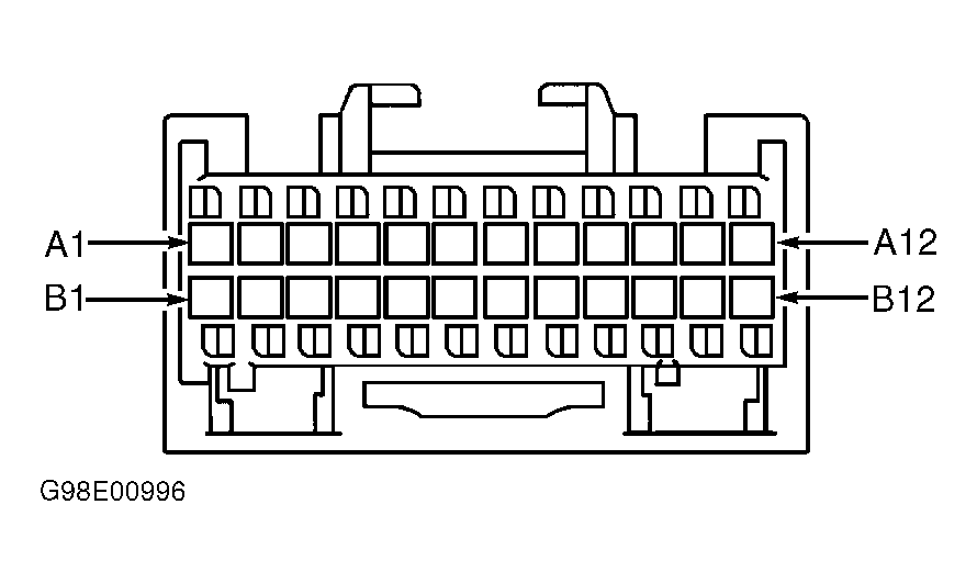 Courtesy of GENERAL MOTORS CORP.