Fuel Gauge Is Inaccurate (Diesel Engine)
- With known amount of fuel in tank, check gauge readings. If gauge reads significantly different than known amount, go to next step. If gauge is reasonable accurate, system is okay.
- Disconnect fuel tank level sender harness connector on top of fuel tank. Turn ignition to RUN position. Using Tester (J-33431-B), jumper tester leads to Purple and Black wire terminals of harness connector. Set dial to 40 ohms. Slowly rotate dial to 250 ohms. If fuel gauge reads EMPTY, then FULL, replace fuel tank level sender. If gauge does not respond, go to next step.
- Turn ignition off. Disconnect EVO/Passlock™ module harness connector. Connect fused jumper wire between EVO/Passlock™ harness connector terminal No. B1 (Black/White wire) and ground. See Fig 1. Turn ignition switch to RUN position. Using Tester (J-33431-B), set dial to 40 ohms. Slowly rotate dial to 250 ohms. If fuel gauge reads EMPTY, then FULL, repair open in Black/White. If gauge does not respond, go to next step.
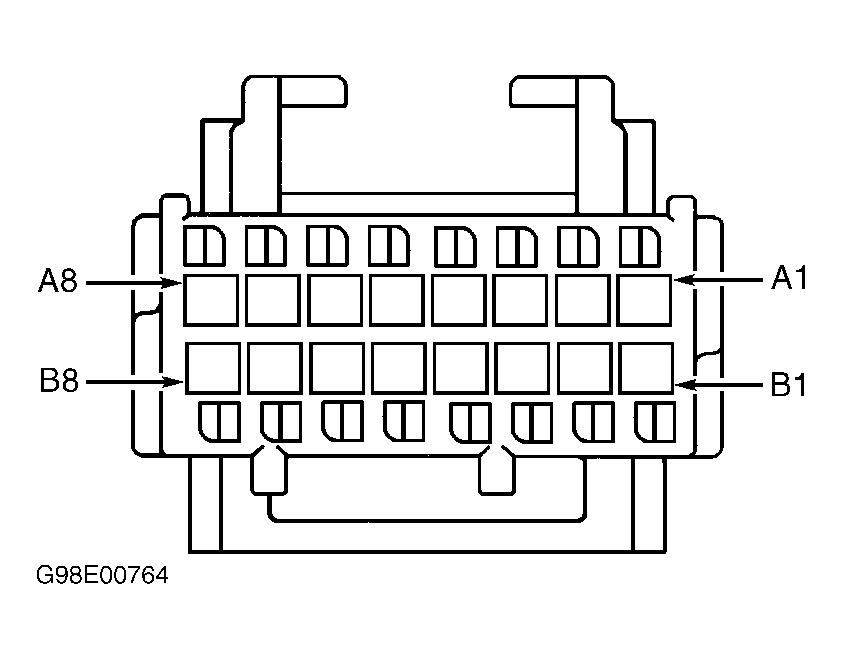 Courtesy of GENERAL MOTORS CORP.
- Remove jumper wire. Connect fused jumper wire between EVO/Passlock™ harness connector terminal No. B5 (Orange/Black wire) and ground. Using Tester (J-33431-B), set dial to 40 ohms. Slowly rotate dial to 250 ohms. If fuel gauge reads EMPTY, then FULL, problem is in Speed Dependent Steering system. See appropriate
STEERING article. If gauge does not respond, go to next step.
- Disconnect tester lead from Black wire at fuel level sender connector. Reconnect tester lead to ground. Set dial to 40 ohms. Slowly rotate dial to 250 ohms. If fuel gauge reads EMPTY, then FULL, repair open in Black wire between fuel level sender and EVO/Passlock™ module. If gauge does not respond, go to next step.
- Turn ignition off. Reconnect EVO/Passlock™ module harness connector and fuel level sender harness connector. Disconnect fuel sender buffer module harness connector. Using Tester (J-33431-B), jumper leads between fuel buffer harness connector terminal "L" (Purple wire) and ground. See Fig 2. Set dial to 40 ohms. Slowly rotate dial to 250 ohms. If fuel gauge reads EMPTY, then FULL, go to next step. If gauge does not respond, go to step 10.
 Courtesy of GENERAL MOTORS CORP.
- Using voltmeter, backprobe fuel buffer module harness connector terminal "A" (Pink wire) with positive lead, and connect negative lead to ground. Measure voltage. If voltage is more than 10 volts, go to next step. If voltage is less than 10 volts, repair open in Pink wire.
- Using voltmeter, backprobe fuel buffer module harness connector terminal "B" (Gray wire) with positive lead, and connect negative lead to ground. Measure voltage. If voltage is between 4.5-5.5 volts, go to step 10. If voltage is not between 4.5-5.5 volts, go to next step.
- Using voltmeter, backprobe EVO/Passlock™ module harness connector terminal No. B6 (Gray wire) with positive lead, and connect negative lead to ground. See Fig 1. Measure voltage. If voltage is between 4.5-5.5 volts, repair open in Gray wire. If voltage is not between 4.5-5.5 volts, problem is in Speed Dependent Steering system. See appropriate
STEERING article.
- Disconnect EVO/Passlock™ module harness connector. Using ohmmeter, measure resistance between EVO/Passlock™ module harness connector terminal "M" (Black/White wire) and ground. If resistance is less than 5 ohms, replace fuel sender buffer module. If resistance is more than 5 ohms, repair open in Black/White wire.
- Reconnect all disconnected components. Disconnect instrument cluster harness connector. Connect a fused jumper wire between instrument cluster harness connector terminal No. B17 (Pink wire) and instrument cluster connector terminal No. B17. Connect second fused jumper wire between instrument cluster harness connector terminal No. B13 (Black wire) and instrument cluster connector terminal No. B13. Using Tester (J-33431-B), connect Red tester lead to instrument cluster connector cavity B2 (Purple wire) and other lead to ground. Set dial to 40 ohms. Slowly rotate dial to 250 ohms. If fuel gauge reads EMPTY, then FULL, repair open in Purple wire. If gauge does not respond, go to next step.
- Connect a fused jumper wire between instrument cluster harness connector terminal No. B17 (Pink wire) and battery power. Connect second fused jumper wire between instrument cluster harness connector terminal No. B13 (Black wire) and instrument cluster connector terminal No. B13. Using Tester (J-33431-B), connect Red tester lead to instrument cluster connector cavity B2 (Purple wire) and other lead to ground. Set dial to 40 ohms. Slowly rotate dial to 250 ohms. If fuel gauge reads EMPTY, then FULL, repair open in Pink wire. If gauge does not respond, go to next step.
- Using ohmmeter, measure resistance between instrument cluster harness connector terminal No. B13 (Black/White or Tan/White wire) and ground. If resistance is less than 5 ohms, replace instrument cluster. See INSTRUMENT CLUSTER under REMOVAL & INSTALLATION. If resistance is more than 5 ohms, repair open in Black/White or Tan/White wire.