Brake Warning Light Inoperative (Without Audible Brake Warning)
- If warning light is inoperative with parking brake only, go to step 3. If warning light is inoperative when ignition is cycled only (ABS self-test), go to step 4. If warning light is inoperative with low fluid pressure only, go to step 5. If warning light is inoperative when ignition switch is in bulb test position only, go to step 6. If warning light is completely inoperative, go to step 7. If warning light is inoperative for all condition except parking brake, go to next step.
- Check for open in Tan/White wire between Diode 1 and Daytime Running Lights (DRL) module. Also, check for open in Purple wire between Diode 1 and splice S157 located in engine harness, near EBCM breakout. If Tan/White wire and Purple wire are okay, replace Diode 1.
- Disconnect park brake warning switch connector. Turn ignition on. Connect a fused jumper between park brake warning switch connector terminal "A" (Light Blue wire) and ground. If warning light illuminates, check park brake warning switch adjustment. Also, check park brake warning switch connection to ground. If adjustment and connection are okay, replace park brake warning switch. If warning light does not illuminate, repair open in Light Blue wire between park brake warning switch and DRL module.
- Locate Electronic Brake Control Module (EBCM) near brake master cylinder. Disconnect EBCM 10-pin connector C1. Turn ignition on. Connect a fused jumper wire between EBCM connector C1 terminal "H" (Purple wire) and ground. See Fig 1. If warning light illuminates, diagnose Anti-Lock Brake System (ABS). See appropriate
ANTI-LOCK article in BRAKES. If warning light does not illuminate, repair open in Purple wire between EBCM and splice S157 located in engine harness, near EBCM breakout.
- Disconnect brake pressure warning switch connector. Turn ignition on. Connect a fused jumper wire between brake pressure warning switch connector terminal "A" (Purple wire) and ground. If warning light illuminates, check for open in Black wire between brake pressure warning switch and ground connection. If Black wire is okay, diagnose combination valve. See appropriate
DISC & DRUM article in BRAKES. If warning light does not illuminate, repair open in Purple wire between brake pressure warning switch and splice S157 located in engine harness, near EBCM breakout
- Using a fuse jumper wire connected to ground, backprobe ignition switch connector terminal B5 (Light Blue wire). Turn ignition switch to bulb test position. If warning light illuminates, check for open in Black wire between ignition switch and ground connection. If Black wire is okay, replace ignition switch. If warning light does not illuminate, repair open in Light Blue wire between DRL module and ignition switch.
- Disconnect instrument cluster connector. Turn ignition on. Connect a test light between instrument cluster connector terminal No. 22 (Pink wire) and ground. See Fig 2. If test light illuminates, check for open in Black wire between brake pressure warning switch and ground connection. Also, check for open in Tan/White wire between instrument cluster and DRL module. If Purple wire and Tan/White wire are okay, replace DRL module. If test light does not illuminate, repair open in Pink wire between instrument panel fuse block and instrument cluster.
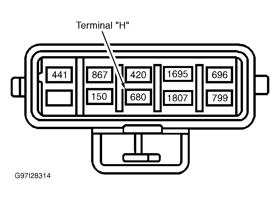 Courtesy of GENERAL MOTORS CORP.
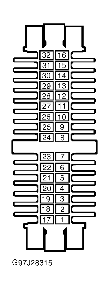 Courtesy of GENERAL MOTORS CORP.