Bushing Replacement (G35/3500 & P35/3500)
- Raise and support vehicle under frame, with control arms hanging free. Remove wheel and tire assembly. Disconnect shock absorber and stabilizer bar at lower control arm.
- Place jack under lower control arm. Jack must be positioned inward of coil spring and in depression areas of control arm. Install safety chain over upper control arm on inside of stabilizer bar and outside of shock absorber.
- Remove lower control arm "U" bolt nuts and washers. Slowly lower the control arm from frame releasing coil spring tension. Remove grease fittings. Remove bushing nuts and remove lower control arm shaft from control arm. Remove seals located between bushing and lower control arm shaft.
- To install, slide NEW seals onto lower control arm shaft. Install shaft into lower control arm. Adjust shaft until centered in control arm, then tighten bushing nuts to specification. See Fig 1. See TORQUE SPECIFICATIONS table at the end of this article. Check shaft for free rotation. Install grease fittings and lubricate bushings.
- Install lower control arm. Ensure front indexing hole in lower control arm shaft aligns with crossmember attaching stud. To complete installation, reverse removal procedure. Tighten bolts and nuts to specification. See TORQUE SPECIFICATIONS table at the end of this article. Lower vehicle and check wheel alignment. See SPECIFICATIONS & PROCEDURES article in WHEEL ALIGNMENT.
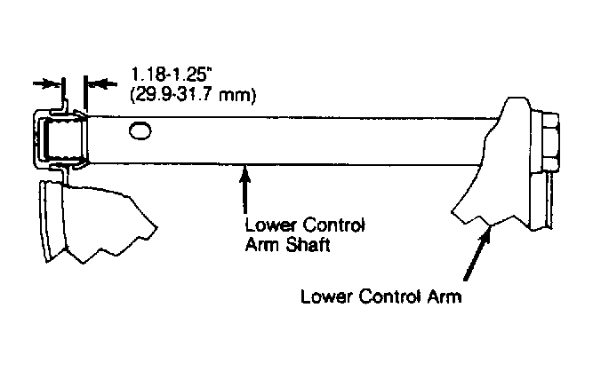 Courtesy of GENERAL MOTORS CORP.