Pinion Depth Adjustment
- Clean all drive axle housing bearing race bores. Ensure drive pinion bore is free of nicks and dirt. Install Master Drive Pinion Block (D-120
) for 9 3/4" drive axle or (D-6255
) 10 1/2" and 11" drive axles into pinion bore. See Fig 1. Assemble Master Discs (D-116-2
) onto Arbor (D-115-3
). Install arbor and disc assembly into drive axle housing. See Fig 1.
- Place Pinion Height Block (D-116-1
) on top of master drive pinion block and against arbor. See Fig 1. Place Dial Indicator Block (D-115
) on lowest step of pinion height block. While applying a downward pressure on dial indicator block, set dial indicator to zero.
- Slide dial indicator block over to arbor. Move dial indicator block back and forth (perpendicular to arbor) to get highest reading. This reading, added together with "plus or minus figure" etched on drive pinion head, is thickness of shim pack necessary for proper pinion depth adjustment. See Fig 2.
- Measure each shim thickness. Add thickness of shims to obtain total shim pack thickness. If necessary, baffle or slinger thickness must also be included in shim pack thickness.
NOTE:
A positive (+) value figure on drive pinion head indicates distance between ring gear centerline and drive pinion must be increased by number of thousandths marked on pinion head. A negative (--) value figure indicates distance must be decreased. A zero (0) figure etched on drive pinion means to use shim thickness as determined by this procedure. See Fig 2.
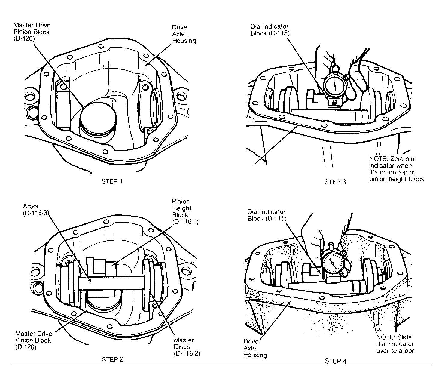 Courtesy of GENERAL MOTORS CORP.
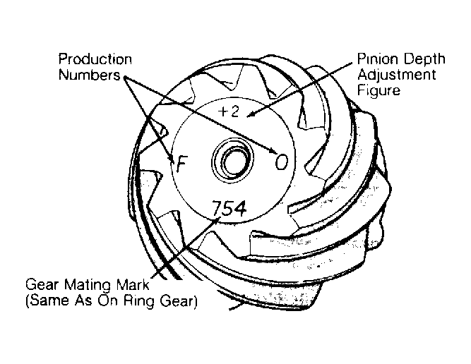 Courtesy of CHRYSLER CORP.