Valve Clearance
WARNING: This page is about a different car, the 1995 Dodge Pickup and 1995 Dodge Cab & Chassis. However, it is still accessible from the selected car via links, so may be relevant.
NOTE:
Valve clearance must be adjusted with engine temperature less than 140°F (60°C).
- Engine can be rotated by removing dust cover from transmission adapter plate and installing Engine Barring Tool (7471B) in transmission adapter plate. See Fig 1
.
CAUTION:
Use care when engaging timing pin to avoid breaking tip of timing pin. Ensure timing pin is disengaged before rotating engine.
- Note location of timing pin. See Fig 1
. Push timing pin to ward front of engine. Slowly rotate engine clockwise (viewed from front of engine) while holding tension on timing pin. Rotate engine until timing pin engages machined hole on camshaft gear and No. 1 cylinder is at TDC.
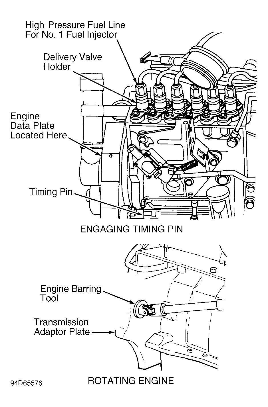 Courtesy of CHRYSLER CORP.
- Remove nameplate, located above rocker lever covers. Remove rocker lever covers and gaskets. Ensure No. 1 cylinder push rods are loose and valves are closed. If No. 1 cylinder push rods are not loose or valves are not closed, disengage timing pin. Rotate engine 360 degrees. Engage timing pin.
- With No. 1 cylinder at TDC, check valve clearance on proper valves. See VALVE ADJUSTING SEQUENCE
table. If valve clearance is not as specified, adjust valve clearance using rocker lever adjusting screw. See VALVE CLEARANCE SPECIFICATIONS
table.
- Once valve clearances are checked and adjusted on proper valves, place reference marks on vibration damper and front timing gear cover. Disengage timing pin. Rotate crankshaft clockwise 360 degrees and realign reference marks.
- Check valve clearance on proper valves. See VALVE ADJUSTING SEQUENCE table. Adjust valve clearance if not within specification. See VALVE CLEARANCE SPECIFICATIONS
table.
- Using NEW gaskets, install rocker lever covers. Install and tighten rocker lever cover bolts to specification. See TORQUE SPECIFICATIONS
. Install nameplate.
VALVE ADJUSTING SEQUENCE
| Procedure |
Cylinder Number |
| Step 1 |
| Exhaust Valve |
1, 3 & 5 |
| Intake Valve |
1, 2 & 4 |
| Step 2 |
| Exhaust Valve |
2, 4 & 6 |
| Intake Valve |
3, 5 & 6 |
VALVE CLEARANCE SPECIFICATIONS
| Application |
In. (mm) |
| Exhaust Valve |
.020 (.51) |
| Intake Valve |
.010 (.25) |