Determining Total Differential Shim Pack
- Ensure drive pinion is out of drive axle housing. On 9 3/4" drive axle, install assembled differential case, with Master Differential Bearings (D-117) installed, in drive axle housing. On 10 1/2" drive axle, install assembled differential case, with Master Differential Bearings (D-136) installed, in drive axle housing. Mount dial indicator on ring gear bolt side of differential case. See Fig 1.
- On 10 1/2" heavy duty drive axles, install outboard spacer between master bearing (ring gear side) and drive axle housing. On all axles, force differential assembly toward dial indicator as far as possible.
- Preload dial indicator to one half of its travel. Place tip of dial indicator on a machined (flat) differential surface, just next to ring gear bolt. Mark this location with chalk. Set dial indicator to zero.
- Force differential assembly in opposite direction of dial indicator as far as it will go. Repeat this step until same reading is obtained. Record the number of thousandths that the dial indicator traveled, NOT the reading on dial.
- On 9 3/4" and 10 1/2" light duty (model "B" and "U") drive axles, the reading obtained in step 4) will determine the thickness of shim pack to be used without any bearing preload, which will be added later.
- On 10 1/2" heavy duty drive axles, the reading obtained in step 4) plus the spacer thickness will determine the thickness of shims and spacer to be used.
- On all axles, remove dial indicator from drive axle housing. Remove differential case from drive axle housing. DO NOT
remove master bearings from differential case assembly.
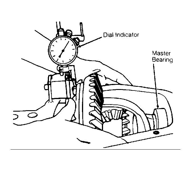 Courtesy of GENERAL MOTORS CORP.