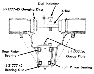
- Drive pinion rear bearing shim thickness, controlling pinion depth of mesh with ring gear, must be determined whenever a new axle housing, ring and pinion set, or pinion bearings and cups are installed. Depth of mesh is determined by using suitable gauging tool (J-21777).
- If removed, install pinion bearing cups into housing, then place lubricated pinion bearings into cups. Position gauge plate (J-21777-36) and rear pinion bearing pilot (if used) on preload stud, then install through rear pinion bearing and through front pinion bearing and front pinion bearing disc (J-21777-42). Install hex nut until snug, then rotate bearings to insure proper seating. Hold preload stud stationary with a wrench on flats, then tighten hex nut until 20 in. lbs. are required to rotate bearings.
- Mount side bearing gauging discs (J-21777-45) on ends of arbor, then place arbor into carrier making sure discs are properly seated. Install side bearing caps and bolts, then tighten bolts to avoid movement. Position dial indicator on mounting post of arbor, with contact button resting on top surface of plunger. Preload dial indicator 1/2 revolution, then tighten in this position.
- Place plunger onto gauging area of gauge plate. Rock plunger rod slowly back and forth across gauging area until dial indicator reads greatest deflection, then set indicator to zero. Repeat rocking action several times to verify setting. Once zero reading is obtained, swing plunger until it is removed from gauging area. Dial indicator will now read required pinion shim thickness for a "nominal pinion". Record this reading.
- Check drive pinion for painted or stamped markings on pinion stem, or a stamped code number on small end of pinion gear. If marking is found to be plus or minus number (for example, +2 or -5) add or subtract that many thousandths from indicator reading. This will then be thickness of rear pinion bearing shim pack.
NOTE:
If no markings are found on pinion, use dial indicator reading as shim thickness.
- If marking is found to be a code number, see following chart, then add or subtract correct number of thousandths from dial indicator reading.
NOTE:
All production pinions are "nominal" pinions and may not be marked "45".
| Pinion Code |
Correction Required |
| 40 |
Subtract.005" |
| 41 |
Subtract.004" |
| 42 |
Subtract.003" |
| 43 |
Subtract.002" |
| 44 |
Subtract.001" |
| 45 |
No Correction |
| 46 |
Add.001" |
| 47 |
Add.002" |
| 48 |
Add.003" |
| 49 |
Add.004" |
| 50 |
Add.005" |
- Remove bearing caps and gauging tool from housing. Place selected shim pack on pinion gear, then install lubricated pinion bearing onto pinion gear shaft using suitable press.
 Courtesy of GENERAL MOTORS COMPANY
- Install a new collapsible spacer over pinion gear shaft, then position pinion assembly in housing. While holding pinion forward, carefully drive front pinion bearing onto pinion gear shaft until a few threads are exposed. Install seal, pinion flange, washer and nut, and tighten until all end play is removed. Rotate pinion several times to seat bearings, then check preload using an INCH lb. torque wrench. Continue tightening nut and checking preload until specified preload is obtained.
CAUTION:
Do not back off nut to lessen preload. If preload is exceeded, a new collapsible spacer must be installed and nut retightened until proper preload is obtained.