Pinpoint Test A: The Heated Seats Are Inoperative - Driver And Passenger Seats
- A1 CHECK FOR VOLTAGE TO THE DRIVER HEATED SEAT RELAY
- Disconnect: Driver Heated Seat Relay.
- Ignition ON.
- Measure the voltage between driver heated seat relay socket pin 1, circuit CBP17 (BN/GN), and ground.
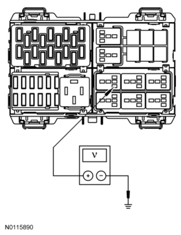 Courtesy of FORD MOTOR CO.
- Is the voltage greater than 10 volts?
- Yes
: GO to A2.
- No
: VERIFY Central Junction Box (CJB) fuse 17 (7.5A) is OK. If OK, REPAIR the circuit. If not OK, REFER to the OEM WIRING DIAGRAMS
article
to identify the possible causes of the circuit short. TEST the system for normal operation.
- A2 CHECK THE HEATED SEAT SWITCH GROUND CIRCUIT
- Ignition OFF.
- Disconnect: Driver Heated Seat Switch C2400.
- Measure the resistance between driver heated switch C2400-4, circuit GD115 (BK/GY), harness side and ground.
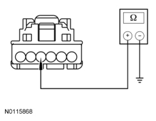 Courtesy of FORD MOTOR CO.
- Is the resistance less than 5 ohms?
- Yes
: GO to A3.
- No
: REPAIR the circuit. TEST the system for normal operation.
- A3 CHECK THE BCM FOR CORRECT OPERATION
- Disconnect all of the BCM connectors.
- Check for:
- corrosion.
- pushed-out pins.
- Connect all of the BCM connectors and make sure they seat correctly.
- Operate the system and verify the concern is still present.
- Is the concern still present?
- Yes
: INSTALL a new BCM. REFER to
MULTIFUNCTION ELECTRONIC MODULES
. TEST the system for normal operation.
- No
: The system is operating correctly at this time. The concern may have been caused by a loose or corroded connector. CLEAR the DTCs. REPEAT the self-test. TEST the system for normal operation.