Pinpoint Test D: B10D7:87
- D1 CHECK THE PATS TRANSCEIVER VOLTAGE SUPPLY CIRCUIT FOR VOLTAGE
- Ignition OFF.
- Disconnect: PATS Transceiver C252.
- Ignition ON.
- Measure the voltage
between:
| Positive Lead |
Negative Lead |
| Pin |
Circuit |
Pin |
Circuit |
| C252-1 |
CBP59 (BN/WH) |
- |
Ground |
 Courtesy of FORD MOTOR CO.
- Is the voltage greater than 11 volts?
- Yes
: GO to D3.
- No
: VERIFY the BCM fuse 59 (5A) is OK. If OK, GO to D2. If not OK, REFER to the appropriate SYSTEM WIRING DIAGRAMS
to identify the possible causes of the circuit short.
- D2 CHECK THE PATS TRANSCEIVER VOLTAGE SUPPLY CIRCUIT FOR AN OPEN
- Ignition OFF.
- Disconnect: BCM C2280F.
- Ignition ON.
- Measure the resistance
between:
| Positive Lead |
Negative Lead |
| Pin |
Circuit |
Pin |
Circuit |
| C252-1 |
CBP59 (BN/WH) |
C2280F-10 |
CBP18 (GY/OG) |
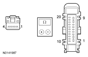 Courtesy of FORD MOTOR CO.
- Is the resistance less than 3 ohms?
- Yes
: GO to D6.
- No
: REPAIR the circuit.
- D3 CHECK THE PATS TRANSCEIVER CIRCUITS FOR A SHORT TO VOLTAGE
- Ignition OFF.
- Disconnect: BCM C2280c.
- Disconnect: Ignition Relay.
- Connect a fused jumper wire
between:
| Pin |
Circuit |
Pin |
Circuit |
| 3 |
SBF03 (BU/RD) |
5 |
CDC21 (GN/BN) |
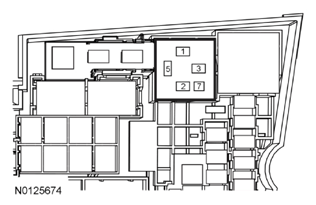 Courtesy of FORD MOTOR CO.
- Measure the voltage
between:
| Positive Lead |
Negative Lead |
| Pin |
Circuit |
Pin |
Circuit |
| C252-2 |
RRT25 (VT/WH) |
- |
Ground |
| C252-3 |
VRT24 (YE/OG) |
- |
Ground |
| C252-4 |
VRT23 (VT/GY) |
- |
Ground |
 Courtesy of FORD MOTOR CO.
- Is any voltage present?
- Yes
: REMOVE the jumper wire. REPAIR the affected circuit.
- No
: REMOVE the jumper wire. GO to D4.
- D4 CHECK THE PATS TRANSCEIVER CIRCUITS FOR A SHORT TO GROUND
- Measure the resistance
between:
| Positive Lead |
Negative Lead |
| Pin |
Circuit |
Pin |
Circuit |
| C252-2 |
RRT25 (VT/WH) |
- |
Ground |
| C252-3 |
VRT24 (YE/OG) |
- |
Ground |
| C252-4 |
VRT23 (VT/GY) |
- |
Ground |
 Courtesy of FORD MOTOR CO.
- Are the resistances greater than 10, 000 ohms?
- Yes
: GO to D5.
- No
: REPAIR the affected circuit.
- D5 CHECK THE PATS TRANSCEIVER CIRCUITS FOR AN OPEN
- Measure the resistance
between:
| Positive Lead |
Negative Lead |
| Pin |
Circuit |
Pin |
Circuit |
| C252-2 |
RRT25 (VT/WH) |
C2280C-30 |
GD133 (BK) |
| C252-3 |
VRT24 (YE/OG) |
C2280C-54 |
VRT24 (YE/OG) |
| C252-4 |
VRT23 (VT/GY) |
C2280C-34 |
VRT23 (VT/GY) |
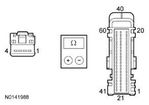 Courtesy of FORD MOTOR CO.
- Are the resistances less than 3 ohms?
- Yes
: INSTALL a new PATS transceiver. REFER to PASSIVE ANTI-THEFT SYSTEM (PATS) TRANSCEIVER . CLEAR the DTCs and WAIT 10 seconds. REPEAT the BCM self-test. If DTC B10D7:87 is retrieved again, GO to D6.
- No
: REPAIR the affected circuit.
- D6 CHECK FOR CORRECT BCM OPERATION
- Disconnect and inspect all the BCM connectors.
- Repair:
- corrosion (install new connector or terminals - clean module pins)
- damaged or bent pins - install new terminals/pins
- pushed-out pins - install new pins as necessary
- Reconnect the BCM connectors. Make sure they seat and latch correctly.
- Operate the system and determine if the concern is still present.
- Is the concern still present?
- Yes
: CHECK OASIS for any applicable TSBs. If a TSB exists for this concern, DISCONTINUE this test and FOLLOW TSB instructions. If no TSBs address this concern, INSTALL a new BCM. REFER to
MULTIFUNCTION ELECTRONIC MODULES
.
- No
: The system is operating correctly at this time. The concern may have been caused by module connections. ADDRESS the root cause of any connector or pin issues.