Occupant Classification System (OCS) Sensor - Vehicles With: Multi-Contour Seats: Removal
WARNING: This page is about a different car, the 2015 Ford F-150. However, it is still accessible from the selected car via links, so may be relevant.
WARNING:
The following procedure prescribes critical repair steps required for correct restraint system operation during a crash. Follow all notes and steps carefully. Failure to follow step instructions may result in incorrect operation of the restraint system and increases the risk of serious personal injury or death in a crash.
NOTE:
To prevent system failure, carry out the OCS reset when a front passenger seat cushion is disassembled, a new trim cover is installed or an OCS service kit is installed. Use a scan tool to carry out the OCS reset command.
NOTE:
The cushion heater mat and multi-contour seat cushion adjuster on a front outboard passenger seat are not serviced separately. If a new cushion heater mat or a multi-contour seat cushion adjuster is needed on the front passenger seat, install an OCS service kit equipped with a heater mat or a multi-contour seat cushion adjuster. Failure to follow this instruction may result in incorrect operation of the OCS.
NOTE:
OCS components (seat cushion foam pad, bladder with OCSM) are calibrated to each other and are serviced as an assembly. The OCS components are not to be installed separately. If a new OCS, OCS component or seat cushion foam pad are needed, a new OCS service kit (seat cushion foam pad, bladder with OCSM) must be installed as an assembly.
NOTE:
Seat backrest blower motor without snorkel shown in illustration, unless otherwise called out.
NOTE:
Removal steps in this procedure may contain installation details.
All seats
- 1.
NOTE:
Raise the seat to its highest point of travel.
Remove the front passenger seat. Refer to: Front Seat
.
- 2.
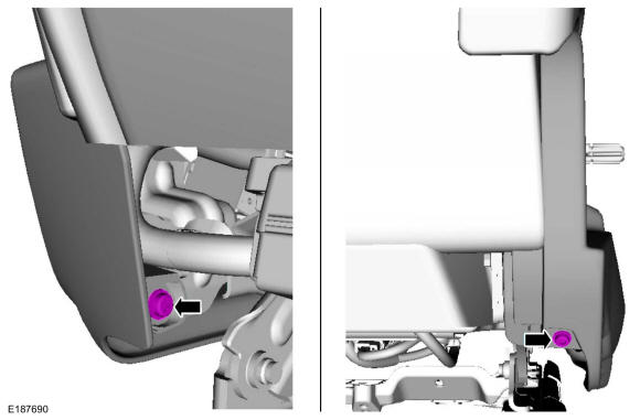
Remove the side shield screws.
 Courtesy of FORD MOTOR COMPANY Courtesy of FORD MOTOR COMPANY
|
- 3.
- 1.
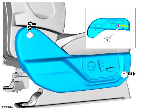
Lift up on the rear of the side shield and pull outward.
- 2.
Push the side shield forward.
- 3.
Disconnect the electrical connector and remove the side shield.
 Courtesy of FORD MOTOR COMPANY Courtesy of FORD MOTOR COMPANY
|
- 4.
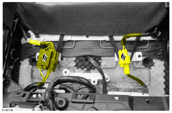
Detach the electrical connector retainers and position the wire harnesses aside.
 Courtesy of FORD MOTOR COMPANY Courtesy of FORD MOTOR COMPANY
|
- 5.
NOTE:
Seat backrest blower motor with snorkel shown in illustration.
- 1.
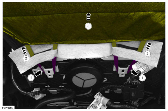
Detach the backrest cover straps.
- 2.
If equipped, route the backrest cover straps through the backrest blower motor snorkel.
- 3.
Position the backrest cover upward.
 Courtesy of FORD MOTOR COMPANY Courtesy of FORD MOTOR COMPANY
|
- 6.
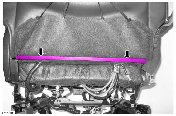
Detach the backrest cover lower J-clips.
 Courtesy of FORD MOTOR COMPANY Courtesy of FORD MOTOR COMPANY
|
- 7.
NOTE:
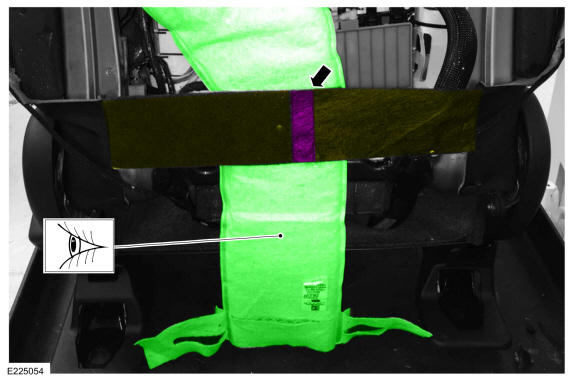
Seat backrest blower motor with snorkel shown in illustration.
NOTE:
For installation of a backrest blower motor with snorkel, note the routing of the snorkel.
Detach the hook-and-loop retainer and position the backrest cover strap aside.
 Courtesy of FORD MOTOR COMPANY Courtesy of FORD MOTOR COMPANY
|
- 8.
- 1.
NOTE:
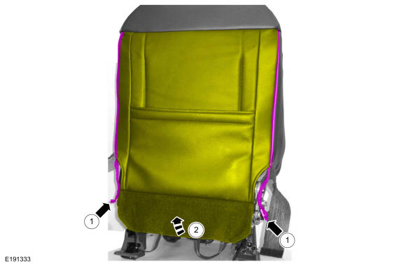
To install, gradually alternate the left and right seat backrest cover zippers to prevent damage to the seat backrest cover.
Unzip the backrest cover zipper on each side.
- 2.
Position the backrest cover up.
 Courtesy of FORD MOTOR COMPANY Courtesy of FORD MOTOR COMPANY
|
- 9.
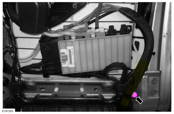
Detach the multi-contour seat cushion hose retainer.
 Courtesy of FORD MOTOR COMPANY Courtesy of FORD MOTOR COMPANY
|
- 10.
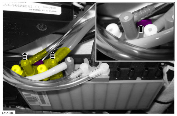
Release the locking tab, and disconnect the hose coupling assembly (orange) from the SCMH.
 Courtesy of FORD MOTOR COMPANY Courtesy of FORD MOTOR COMPANY
|
- 11.
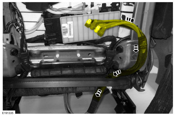
Feed the multi-contour seat hose assembly out through the backrest cover opening.
 Courtesy of FORD MOTOR COMPANY Courtesy of FORD MOTOR COMPANY
|
- 12.
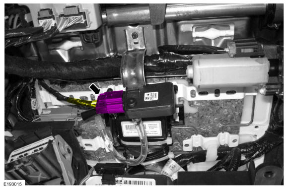
Disconnect the OCS sensor.
 Courtesy of FORD MOTOR COMPANY Courtesy of FORD MOTOR COMPANY
|
- 13.
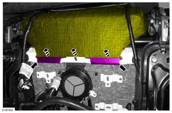
Detach the cushion cover J-clips and position the cushion cover aside.
 Courtesy of FORD MOTOR COMPANY Courtesy of FORD MOTOR COMPANY
|
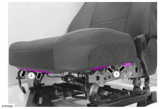
- 14.
- 1.
On both sides, detach the cushion cover J-clips.
- 2.
Detach the cushion cover J-clip.
 Courtesy of FORD MOTOR COMPANY Courtesy of FORD MOTOR COMPANY
|
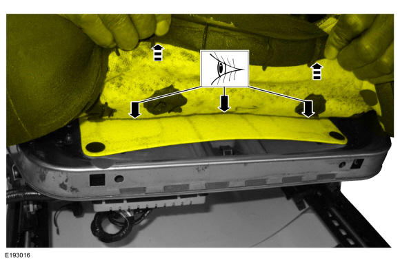
- 15.
Lift the cushion foam pad. If the cushion foam pad, active motion seat cushion adjuster and the OCS are adhered together, then the OCS is a service kit. If nothing is adhered together, then the OCS is OE (original equipment).
 Courtesy of FORD MOTOR COMPANY Courtesy of FORD MOTOR COMPANY
|
Seats with an OE (original equipment) OCS (occupant classification system)
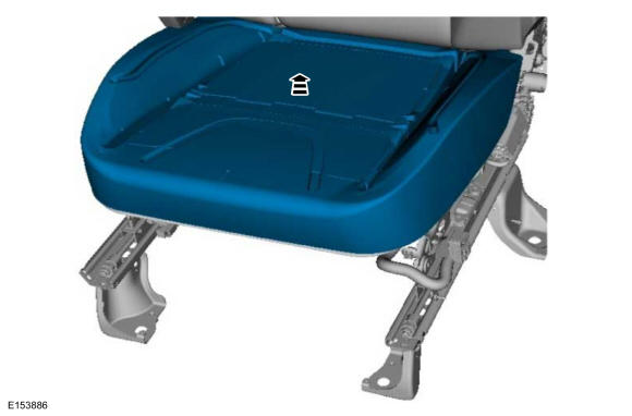
- 16.
Remove the cushion foam pad and cover.
 Courtesy of FORD MOTOR COMPANY Courtesy of FORD MOTOR COMPANY
|
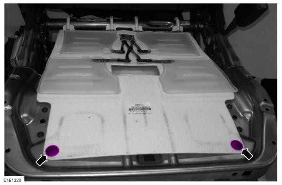
- 17.
Remove the multi-contour seat pin-type retainers.
 Courtesy of FORD MOTOR COMPANY Courtesy of FORD MOTOR COMPANY
|
- 18.
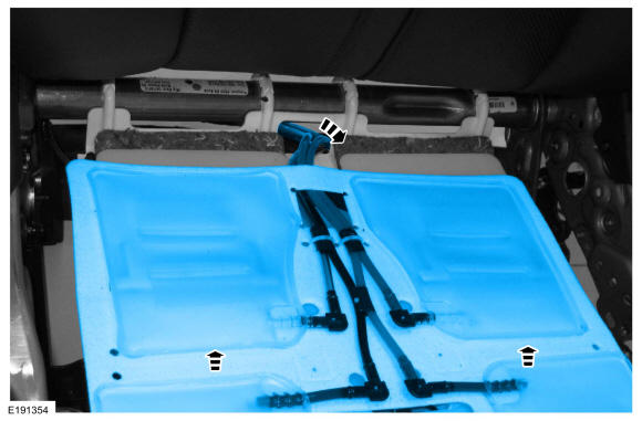
Remove the multi-contour seat cushion bladder assembly and route out the hoses.
 Courtesy of FORD MOTOR COMPANY Courtesy of FORD MOTOR COMPANY
|
- 19.
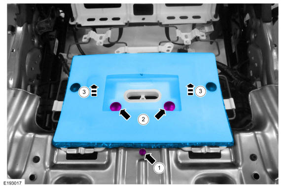
- 1.
Remove the OCS sensor bracket screw.Torque
: 44 lb.in (5 Nm)
- 2.
Remove the OCS pin-type retainers.
- 3.
Lift the OCS up off the seat cushion and start removal.
 Courtesy of FORD MOTOR COMPANY Courtesy of FORD MOTOR COMPANY
|
- 20.
NOTE:
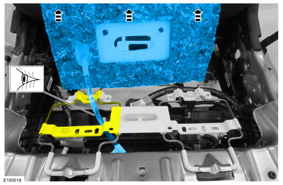
Note the location of the OCS hose as it passes through the seat cushion support for proper installation.
Route out the OCS hose, sensor and sensor bracket from between the seat cushion support wires and remove the OCS.
 Courtesy of FORD MOTOR COMPANY Courtesy of FORD MOTOR COMPANY
|
Seats with a service kit OCS (occupant classification system)
- 21.
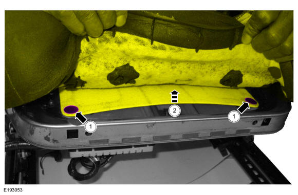
- 1.
Remove the multi-contour seat pin-type retainers.
- 2.
Lift the front of the multi-contour seat assembly to access the OCS pin-type retainers.
 Courtesy of FORD MOTOR COMPANY Courtesy of FORD MOTOR COMPANY
|
- 22.
- 1.
Remove the OCS sensor bracket screw.Torque
: 44 lb.in (5 Nm)
- 2.
Remove the OCS pin-type retainers.
- 3.
Lift the OCS up off the seat cushion and start removal.
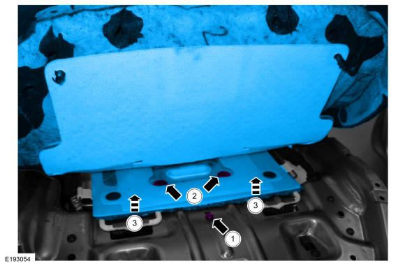 Courtesy of FORD MOTOR COMPANY Courtesy of FORD MOTOR COMPANY
|
- 23.
Route the multi-contour seat hose assembly out from between the seat cushion and backrest.
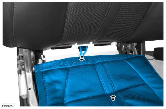 Courtesy of FORD MOTOR COMPANY Courtesy of FORD MOTOR COMPANY
|
- 24.
NOTE:
Note the location of the OCS hose as it passes through the seat cushion support for proper installation.
Route out the OCS hose, sensor and sensor bracket from between the seat cushion support wires and remove the OCS.
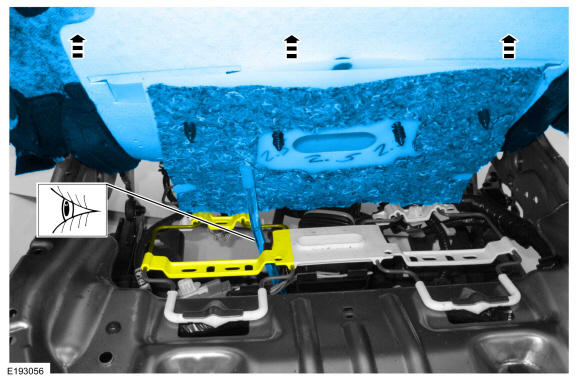 Courtesy of FORD MOTOR COMPANY Courtesy of FORD MOTOR COMPANY
|
All seats
- 25.
NOTE:
This step is only necessary when installing a new OCS.
NOTE:
Follow the unique instructions or graphic for this step in the installation.
Bend the tab up and slide the OCS sensor off the bracket.
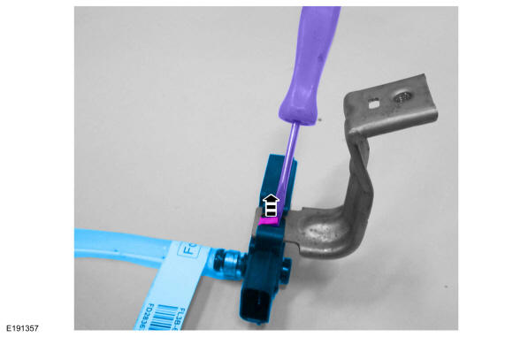 Courtesy of FORD MOTOR COMPANY Courtesy of FORD MOTOR COMPANY
|
- 26.
NOTE:
This step is only necessary when installing a new OCS.
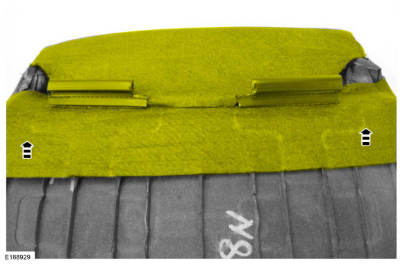
Position the rear portion of the seat cushion cover from the foam.
 Courtesy of FORD MOTOR COMPANY Courtesy of FORD MOTOR COMPANY
|
- 27.
NOTE:
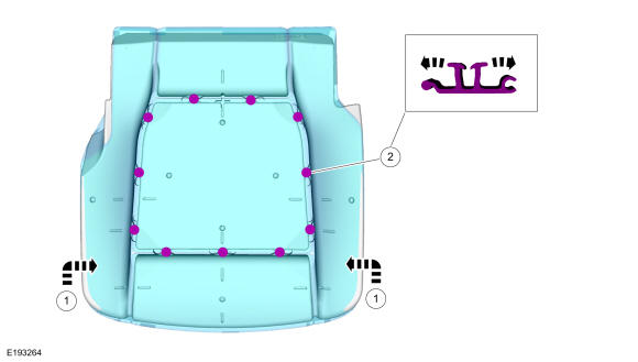
Use care when separating the seat cushion from the hook-and-arrow or the hook may be torn from the seat cushion foam pad.
NOTE:
This step is only necessary when installing a new OCS.
Remove the seat cushion cover.
- 1.
Invert the seat cushion cover.
- 2.
Release the hook-and-arrows.
 Courtesy of FORD MOTOR COMPANY Courtesy of FORD MOTOR COMPANY
|