Transmission - 2.0L Duratec-HE (125kW/170PS) - MI4
WARNING: This page is about a different car, the 2015 Ford Focus. However, it is still accessible from the selected car via links, so may be relevant.
Special Tool(s) / General Equipment
 Courtesy of FORD MOTOR COMPANY Courtesy of FORD MOTOR COMPANY
|
204-605 Separator, Lower Arm Ball Joint |
 Courtesy of FORD MOTOR COMPANY Courtesy of FORD MOTOR COMPANY
|
204-609 Protection Cap, Ball Joint Gaiter |
 Courtesy of FORD MOTOR COMPANY Courtesy of FORD MOTOR COMPANY
|
303-1554 Engine Support Bar |
 Courtesy of FORD MOTOR COMPANY Courtesy of FORD MOTOR COMPANY
|
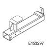
303-1554-03 Adapter for 303-1554 |
 Courtesy of FORD MOTOR COMPANY Courtesy of FORD MOTOR COMPANY
|
303-1554-04 Adapter for 303-1554 |
 Courtesy of FORD MOTOR COMPANY Courtesy of FORD MOTOR COMPANY
|
303-1554-05 Adapter for 303-1554, Engine Support Bar |
 Courtesy of FORD MOTOR COMPANY Courtesy of FORD MOTOR COMPANY
|
303-1554-06 Adapter for 303-1554, Engine Support Bar |
| Ford Diagnostic Equipment |
| Transmission Jack |
| Cable Ties |
| Retaining Strap |
| Wooden Block |
- 1.
NOTE:
TCM Programming is NOT necessary if the transmission is being removed for accessing or servicing the flexplate, rear main seal, clutch, or input shaft seals.
Using the scan tool, recover all module information before removing the transmission. Refer to: Transmission Control Module (TCM) Adaptive Learning . Use the General Equipment: Ford Diagnostic Equipment
- 2.
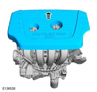
Remove the engine appearance cover.
 Courtesy of FORD MOTOR COMPANY Courtesy of FORD MOTOR COMPANY
|
- 3.
Remove the battery tray. Refer to: Battery Tray
.
- 4.
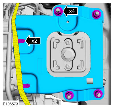
Remove the wiring retainers and the nuts and remove the battery tray support bracket.
 Courtesy of FORD MOTOR COMPANY Courtesy of FORD MOTOR COMPANY
|
- 5.
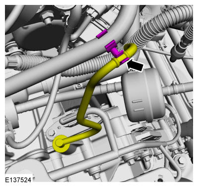
Remove the vent tube from the retainer.
 Courtesy of FORD MOTOR COMPANY Courtesy of FORD MOTOR COMPANY
|
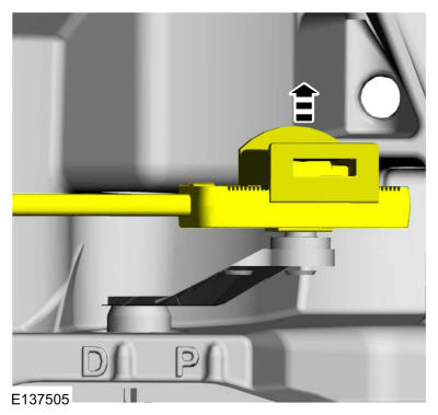
- 6.
Remove the selector lever cable end from the manual lever.
 Courtesy of FORD MOTOR COMPANY Courtesy of FORD MOTOR COMPANY
|
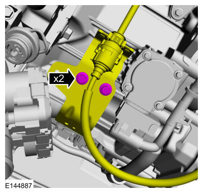
- 7.
Remove the selector lever cable and bracket and position it aside.
 Courtesy of FORD MOTOR COMPANY Courtesy of FORD MOTOR COMPANY
|
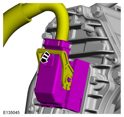
- 8.
NOTE:
Take extra care when handling the component.
Rotate the lever to release the TCM electrical connector.
 Courtesy of FORD MOTOR COMPANY Courtesy of FORD MOTOR COMPANY
|
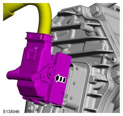
- 9.
NOTE:
Make sure that the terminals or pins/sockets of the TCM and the TCM electrical connector are not bent or damaged.
NOTE:
Take extra care when handling the component terminals.
NOTE:
Take extra care not to damage the wiring harnesses.
Disconnect the TCM electrical connector.
 Courtesy of FORD MOTOR COMPANY Courtesy of FORD MOTOR COMPANY
|
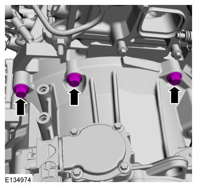
- 10.
Remove the top bellhousing bolts.
 Courtesy of FORD MOTOR COMPANY Courtesy of FORD MOTOR COMPANY
|
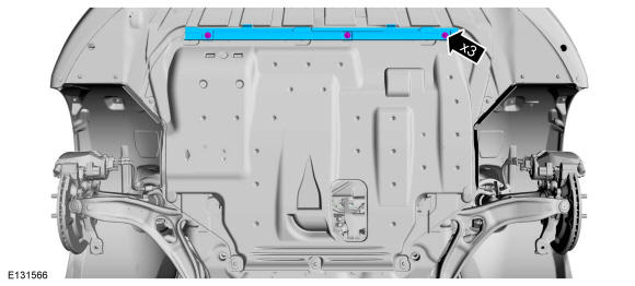
- 11.
Remove the air deflector.
 Courtesy of FORD MOTOR COMPANY Courtesy of FORD MOTOR COMPANY
|
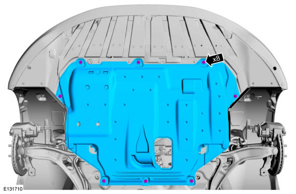
- 12.
Remove the underbody shield.
 Courtesy of FORD MOTOR COMPANY Courtesy of FORD MOTOR COMPANY
|
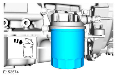
- 13.
Remove the oil filter.
 Courtesy of FORD MOTOR COMPANY Courtesy of FORD MOTOR COMPANY
|
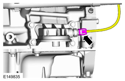
- 14.
Disconnect the oil pressure sensor.
 Courtesy of FORD MOTOR COMPANY Courtesy of FORD MOTOR COMPANY
|
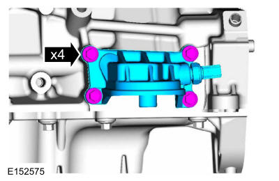
- 15.
Remove the oil filter housing. Discard the gasket.
 Courtesy of FORD MOTOR COMPANY Courtesy of FORD MOTOR COMPANY
|
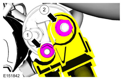
- 16.
Remove the positive battery terminal and the solenoid terminal.
 Courtesy of FORD MOTOR COMPANY Courtesy of FORD MOTOR COMPANY
|
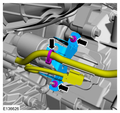
- 17.
NOTE:
Take extra care not to damage the wiring harnesses.
Remove the starter cable retainer.
 Courtesy of FORD MOTOR COMPANY Courtesy of FORD MOTOR COMPANY
|
- 18.
NOTE:
Make sure that the component terminals are not bent or damaged.
Remove the starter.
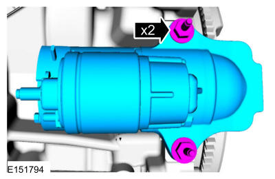 Courtesy of FORD MOTOR COMPANY Courtesy of FORD MOTOR COMPANY
|
- 19.
Remove the starter insulator.
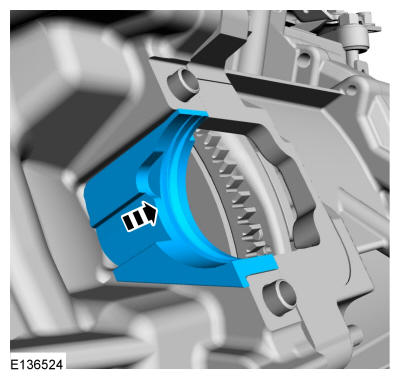 Courtesy of FORD MOTOR COMPANY Courtesy of FORD MOTOR COMPANY
|
- 20.
NOTE:
Note the position of the component before removal.
Remove the ground cable.
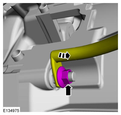 Courtesy of FORD MOTOR COMPANY Courtesy of FORD MOTOR COMPANY
|
- 21.
Remove the bellhousing bolt.
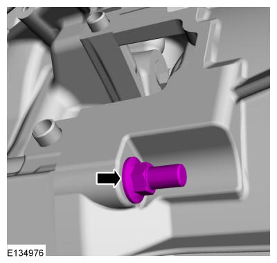 Courtesy of FORD MOTOR COMPANY Courtesy of FORD MOTOR COMPANY
|
- 22.
NOTE:
The transmission fluid should only be drained for a transmission concern. If the transmission is being removed for an engine or clutch concern, it is not necessary to drain the transmission fluid.
NOTE:
The O-ring seal is to be reused unless damaged.
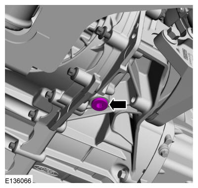
Drain the transmission fluid.
Torque: 32 lb.ft (43 Nm)
 Courtesy of FORD MOTOR COMPANY Courtesy of FORD MOTOR COMPANY
|
- 23.
Remove the front wheels. Refer to: Wheel and Tire
.
- 24.
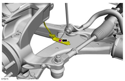
If equipped, remove the LH ride height sensor.
 Courtesy of FORD MOTOR COMPANY Courtesy of FORD MOTOR COMPANY
|
- 25.
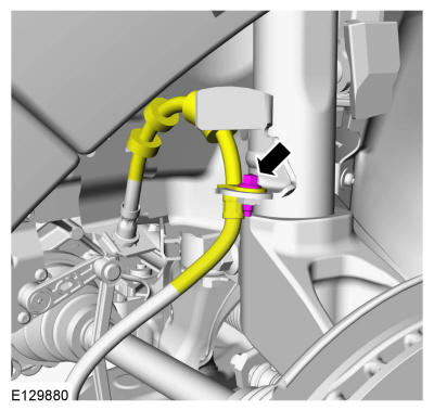
Remove the LH brake hose retainer.
 Courtesy of FORD MOTOR COMPANY Courtesy of FORD MOTOR COMPANY
|
- 26.
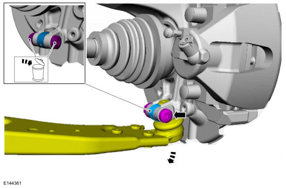
Remove and discard the LH lower control arm nut and bolt.
 Courtesy of FORD MOTOR COMPANY Courtesy of FORD MOTOR COMPANY
|
- 27.
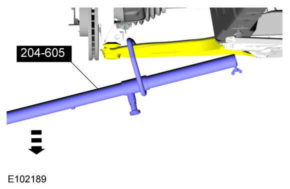
Using the special tool, separate the LH lower control arm from the steering knuckle. Use Special Service Tool: 204-605 Separator, Lower Arm Ball Joint.
 Courtesy of FORD MOTOR COMPANY Courtesy of FORD MOTOR COMPANY
|
- 28.
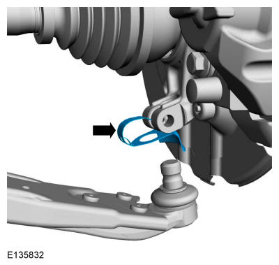
Remove the LH ball joint dust cover.
 Courtesy of FORD MOTOR COMPANY Courtesy of FORD MOTOR COMPANY
|
- 29.
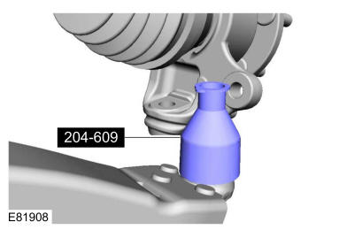
Install the special tool. Use Special Service Tool: 204-609 Protection Cap, Ball Joint Gaiter.
 Courtesy of FORD MOTOR COMPANY Courtesy of FORD MOTOR COMPANY
|
- 30.
NOTE:
Make sure that the strut is not moved more than necessary to prevent damage to top mount.
NOTE:
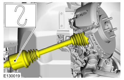
The inner constant velocity (CV) joint must not be bent more than 18 °.
NOTE:
The outer constant velocity (CV) joint must not be bent more than 45 °.
Position aside the LH halfshaft.
 Courtesy of FORD MOTOR COMPANY Courtesy of FORD MOTOR COMPANY
|
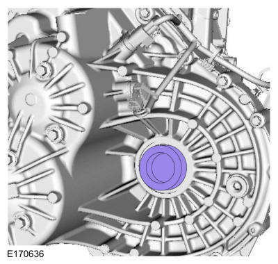
- 31.
Install blanking plug. Use service part F1FZ-7H183-A (FINIS part 5352161).
 Courtesy of FORD MOTOR COMPANY Courtesy of FORD MOTOR COMPANY
|
- 32.
If equipped, remove the RH ride height sensor.
Courtesy of FORD MOTOR COMPANY
|
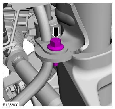
- 33.
Remove the RH brake hose retainer.
 Courtesy of FORD MOTOR COMPANY Courtesy of FORD MOTOR COMPANY
|
- 34.
Remove and discard the RH lower control arm nut and bolt.
Courtesy of FORD MOTOR COMPANY
|
- 35.
Using the special tool, separate the lower control arm from the steering knuckle. Use Special Service Tool: 204-605 Separator, Lower Arm Ball Joint.
Courtesy of FORD MOTOR COMPANY
|
- 36.
Remove the ball joint dust cover.
Courtesy of FORD MOTOR COMPANY
|
- 37.
Install the special tool. Use Special Service Tool: 204-609 Protection Cap, Ball Joint Gaiter.
Courtesy of FORD MOTOR COMPANY
|
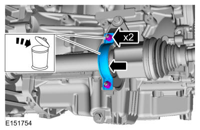
- 38.
Remove and discard the intermediate shaft bearing retaining nuts and strap.
 Courtesy of FORD MOTOR COMPANY Courtesy of FORD MOTOR COMPANY
|
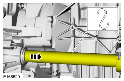
- 39.
Position aside the intermediate shaft. Use the General Equipment: Cable Ties
 Courtesy of FORD MOTOR COMPANY Courtesy of FORD MOTOR COMPANY
|
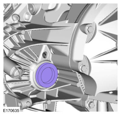
- 40.
Install blanking plug. Use service part F1FZ-7H183-A (FINIS part 5352161).
 Courtesy of FORD MOTOR COMPANY Courtesy of FORD MOTOR COMPANY
|
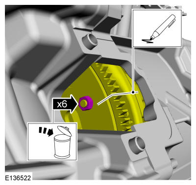
- 41.
NOTE:
Rotate the engine in a clockwise direction only or engine damage may occur.
NOTE:
Note the position of the components before removal.
Index mark the clutch to the flexplate. Remove and discard the flexplate-to-clutch nuts.
 Courtesy of FORD MOTOR COMPANY Courtesy of FORD MOTOR COMPANY
|
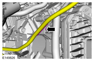
- 42.
Disconnect the wiring retainer and position aside the wiring harness.
 Courtesy of FORD MOTOR COMPANY Courtesy of FORD MOTOR COMPANY
|
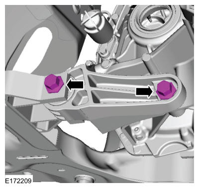
- 43.
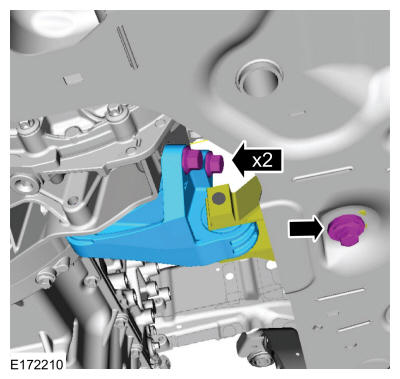
Remove the roll restrictor bracket bolts.
 Courtesy of FORD MOTOR COMPANY Courtesy of FORD MOTOR COMPANY
|
- 44.
Remove the roll restrictor bracket.
 Courtesy of FORD MOTOR COMPANY Courtesy of FORD MOTOR COMPANY
|
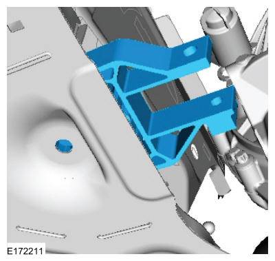
- 45.
Remove the roll restrictor.
 Courtesy of FORD MOTOR COMPANY Courtesy of FORD MOTOR COMPANY
|
- 46.
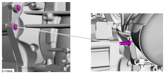
NOTE:
The back bellhousing bolt will stay in the engine after it is unthreaded from the transmission.
Remove the bellhousing bolts.
 Courtesy of FORD MOTOR COMPANY Courtesy of FORD MOTOR COMPANY
|
- 47.
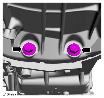
Remove the lower bellhousing bolts.
 Courtesy of FORD MOTOR COMPANY Courtesy of FORD MOTOR COMPANY
|
- 48.
Install the special tools. Use Special Service Tool: 303-1554-05 Adapter for 303-1554, Engine Support Bar., 303-1554-06 Adapter for 303-1554, Engine Support Bar.
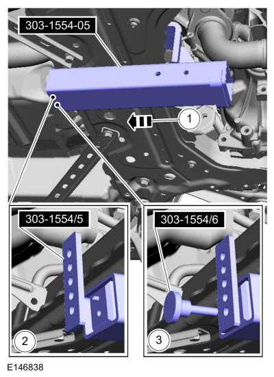 Courtesy of FORD MOTOR COMPANY Courtesy of FORD MOTOR COMPANY
|
- 49.
Install the special tools. Use Special Service Tool: 303-1554 Engine Support Bar.
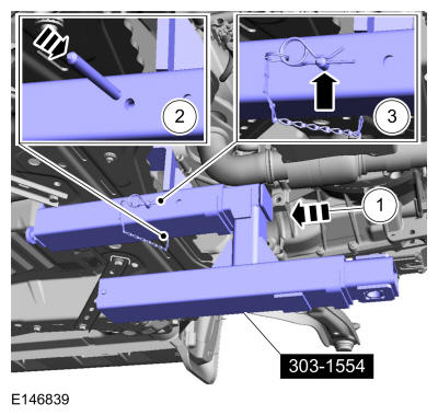 Courtesy of FORD MOTOR COMPANY Courtesy of FORD MOTOR COMPANY
|
- 50.
Install the special tools. Use Special Service Tool: 303-1554-03 Adapter for 303-1554., 303-1554-04 Adapter for 303-1554.
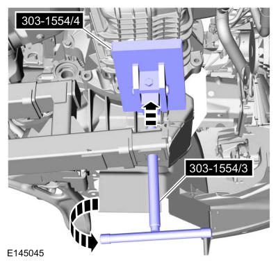 Courtesy of FORD MOTOR COMPANY Courtesy of FORD MOTOR COMPANY
|
- 51.
NOTE:
Use caution when lowering the vehicle after the special tool is installed. If the vehicle is lowered onto the special tool, damage to the special tool or the vehicle can occur.
Rotate the threaded drawbar of the special tool approximately 6 whole rotations after the rubber pad contacts the oil pan. Use Special Service Tool: 303-1554 Engine Support Bar.
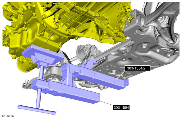 Courtesy of FORD MOTOR COMPANY Courtesy of FORD MOTOR COMPANY
|
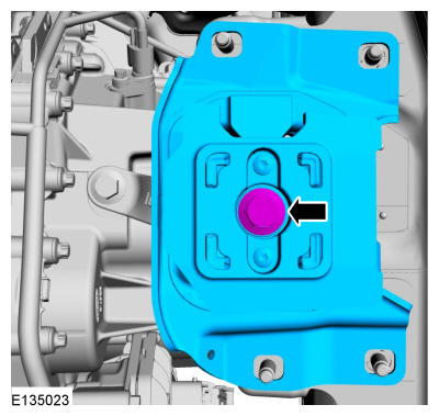
- 52.
Remove the transmission support insulator bolt and remove the transmission support insulator.
 Courtesy of FORD MOTOR COMPANY Courtesy of FORD MOTOR COMPANY
|
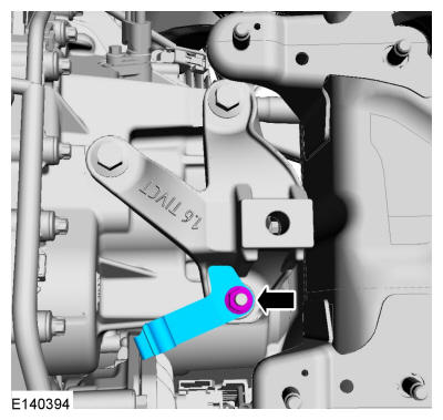
- 53.
Remove the selector lever cable bracket.
 Courtesy of FORD MOTOR COMPANY Courtesy of FORD MOTOR COMPANY
|
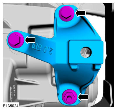
- 54.
Remove the transmission support insulator bracket.
 Courtesy of FORD MOTOR COMPANY Courtesy of FORD MOTOR COMPANY
|
- 55.
NOTE:
Take extra care not to damage the wiring harnesses.
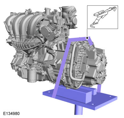
Install the following items:
- Support the transmission with a transmission jack. Use the General Equipment: Transmission Jack. Use the General Equipment: Wooden Block
- Fasten the transmission to the transmission jack with a retaining strap. Use the General Equipment: Retaining Strap
 Courtesy of FORD MOTOR COMPANY Courtesy of FORD MOTOR COMPANY
|
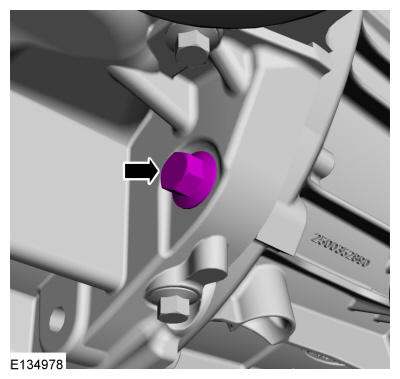
- 56.
Remove the bellhousing bolt.
 Courtesy of FORD MOTOR COMPANY Courtesy of FORD MOTOR COMPANY
|
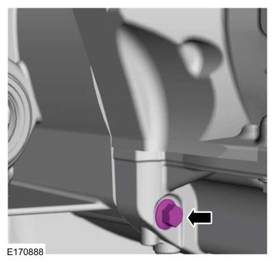
- 57.
Remove the bellhousing bolt.
 Courtesy of FORD MOTOR COMPANY Courtesy of FORD MOTOR COMPANY
|
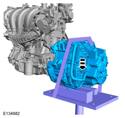
- 58.
NOTE:
Make sure that the locating dowels remain installed.
NOTE:
Make sure that no components catch.
Remove the transmission.
 Courtesy of FORD MOTOR COMPANY Courtesy of FORD MOTOR COMPANY
|