Part 3
Camshaft
Removal
NOTICE: During engine repair procedures, cleanliness is extremely important. Any foreign material, including any material created while cleaning gasket surfaces, that enters the oil passages, coolant passages or the oil pan may cause engine failure.
All camshafts
53. NOTICE: Suspension fasteners are critical parts because they affect performance of vital components and systems and their failure may result in major service expense. New parts must be installed with the same part number or equivalent part, if replacement is necessary. Do not use a replacement part of lesser quality or substitute design. Torque values must be used as specified during reassembly to make sure of correct retention of these parts.
NOTICE: Use care when releasing the lower arm and knuckle into the resting position or damage to the ball joint seal or Constant Velocity (CV) boot may occur.
NOTE: Use the hex-holding feature to prevent the stud from turning while removing the nut.
NOTE: RH shown, LH similar.
Remove and discard the lower ball joint-to-wheel knuckle nuts.
- Separate the lower ball joints from the wheel knuckles.
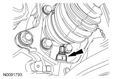
54. Using a wax pencil, mark the relationship of the front subframe to the underbody at the mounting locations.
55. Position the Powertrain Lift under the subframe assembly.
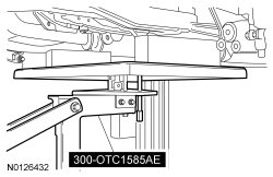
56. NOTE: RH shown, LH similar.
Remove the subframe bracket-to-body bolts.
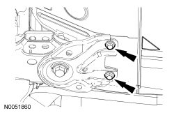
57. NOTE: RH shown, LH similar.
Remove the rear subframe bolts and the subframe brackets.
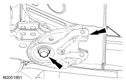
58. NOTE: RH shown, LH similar.
Remove the front subframe bolts.
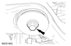
59. Lower the subframe assembly from the vehicle.
60. Pull the RH wheel knuckle outward and rotate it toward the rear of the vehicle.
- Secure the RH wheel knuckle assembly.
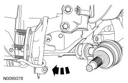
61. Remove the 2 intermediate shaft bracket nuts.
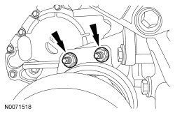
62. Remove the intermediate and halfshaft assembly.
63. NOTICE: The sharp edges on the stub shaft splines can slice or puncture the oil seal. Use care when removing the stub shaft from the transmission or damage to the component may occur.
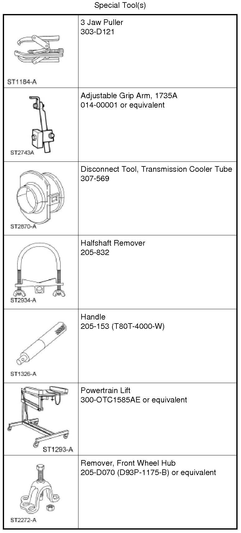
Using the Slide Hammer and Halfshaft Remover, remove the halfshaft from the transmission.
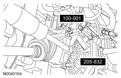
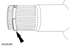
64. Remove and discard the circlip from the stub shaft.
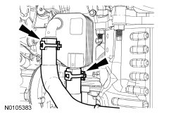
65. If equipped, detach the oil cooler coolant hoses.
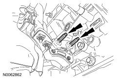
66. Remove the 2 RH halfshaft support bracket studs.
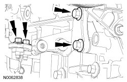
67. Remove the 4 bolts and the RH halfshaft support bracket.
68. Remove the 2 secondary latches from the transmission fluid cooler tubes at the transmission fluid cooler thermal bypass valve.
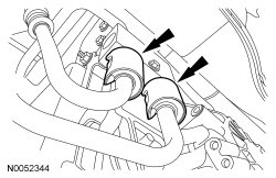
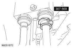
69. Using the Transmission Cooler Tube Disconnect Tool, disconnect the transmission fluid cooler tubes from the transmission fluid cooler thermal bypass valve.
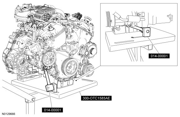
70. NOTE: Position a block of wood under the transaxle.
Install the Powertrain Lift and Adjustable Grip Arms.
71. Remove the transaxle mount through bolt and nut.
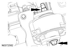
72. Remove the bolt, 3 nuts and the transaxle mount bracket.
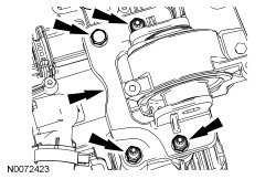
73. Remove the nut, bolt and engine mount brace.
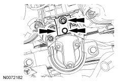
74. Remove the 4 engine mount nuts.
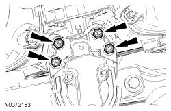
75. Remove the 3 bolts and the engine mount.
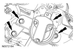
76. Lower the engine and transaxle assembly from the vehicle.
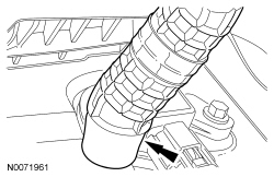
77. Disconnect the PCV hose from the PCV valve.
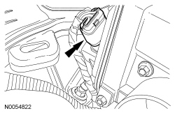
78. Disconnect the Throttle Body (TB) electrical connector.