Part 2
Camshaft
Removal
NOTICE: During engine repair procedures, cleanliness is extremely important. Any foreign material, including any material created while cleaning gasket surfaces, that enters the oil passages, coolant passages or the oil pan may cause engine failure.
All camshafts
27. Disconnect the transaxle control cable from the control lever.
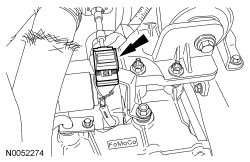
28. Disconnect the transaxle control cable from the shift cable bracket and detach the wiring harness pin-type retainer.
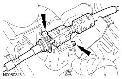
29. If equipped, detach the engine block heater harness from the radiator support.
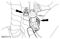
30. Disconnect the A/C pressure switch and remove the nut and disconnect the upper A/C tube from the condenser.
- Discard the O-ring seal.
31. Disconnect the fuel supply tube from the fuel rail.
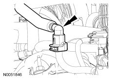
32. Detach the engine wiring harness retainer.
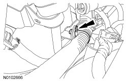
33. Detach the wire harness retainer from the RH valve cover stud bolt.
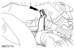
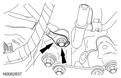
34. Remove the bolt and the ground cable from the engine.
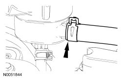
35. Disconnect the hose from the power steering reservoir.
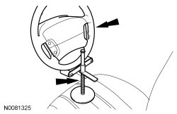
36. NOTE: Use a steering wheel holding device (such as Hunter(R) 28-75-1 or equivalent).
Using a suitable holding device, hold the steering wheel in the straight-ahead position.
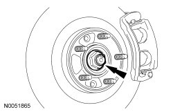
37. NOTE: Apply the brake to keep the halfshafts from rotating.
NOTE: RH shown, LH similar.
Remove the RH and LH halfshaft nuts.
- Do not discard at this time.
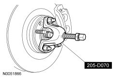
38. NOTE: RH shown, LH similar.
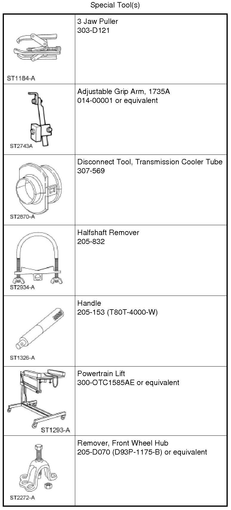
Using the Front Wheel Hub Remover, separate the RH and LH halfshaft from the wheel hubs.
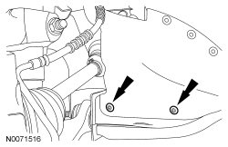
39. Remove the 2 lower scrivets from the rubber shield and position the shield aside.
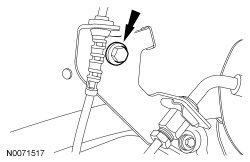
40. Remove the bolt from the RH brake hose bracket.
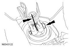
41. NOTICE: Do not allow the intermediate shaft to rotate while it is disconnected from the gear or damage to the clockspring may occur. If there is evidence that the intermediate shaft has rotated, the clockspring must be removed and recentered. For additional information, refer to Restraints and Safety Systems &/or Air Bag Systems.
NOTE: Index-mark the steering column shaft position to the steering gear for reference during installation.
Remove the bolt and disconnect the steering column shaft from the steering gear.
- Discard the bolt.
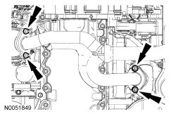
42. Remove the 4 Y-pipe-to-catalytic converter nuts.
- Discard the nuts.
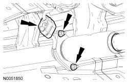
43. Remove the 2 Y-pipe flange nuts.
- Detach the exhaust hanger and remove the Y-pipe.
- Discard the gaskets and nuts.
All-Wheel Drive (AWD) vehicles
44. NOTE: Index-mark the driveshaft for installation.
Remove and discard the 4 bolts and support the driveshaft with a length of mechanic's wire.
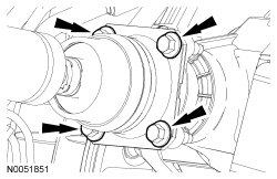
All camshafts
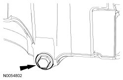
45. Remove the drain plug and drain the engine oil.
- Install the drain plug and tighten to 27 Nm (20 lb-ft).
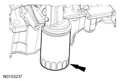
46. Remove and discard the engine oil filter.
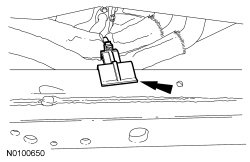
47. If equipped, detach the oil cooler hose support clip from the subframe.
48. Remove the Power Steering Pressure (PSP) tube bracket-to-steering gear bolt.
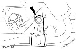
49. Remove the bolt, rotate the clamp plate clockwise and disconnect the PSP (Power Steering Pressure) tube from the steering gear.
- Discard the O-ring seal.
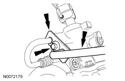
50. Remove the engine roll restrictor-to-subframe through bolt and loosen the engine roll restrictor-to-transaxle bracket through bolt.
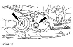
51. NOTE: RH shown, LH similar.
Remove and discard the upper stabilizer link nuts.
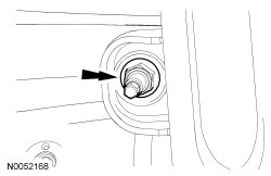
52. NOTE: The hex-holding feature can be used to prevent turning of the stud while removing the nuts.
NOTE: RH shown, LH similar.
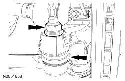
Remove and discard the tie-rod end nuts.
- Separate the tie-rod ends from the wheel knuckles.