Pinpoint Test A: One Or Both Low Beams Are Inoperative
Headlamps
Pinpoint Test A: One Or Both Low Beams Are Inoperative
Normal Operation
When the Body Control Module (BCM) receives a message that the headlamp switch is in the HEADLAMPS ON position and the multifunction switch is in the LOW BEAM position (or the autolamps feature has requested the headlamps on), the BCM (Body Control Module) provides voltage through the headlamp output circuits to the LH and RH low beam headlamps.
The BCM (Body Control Module) also provides an overload protection of the low beam output circuits. When an excessive current draw is detected, the BCM (Body Control Module) disables the affected low beam circuit driver.
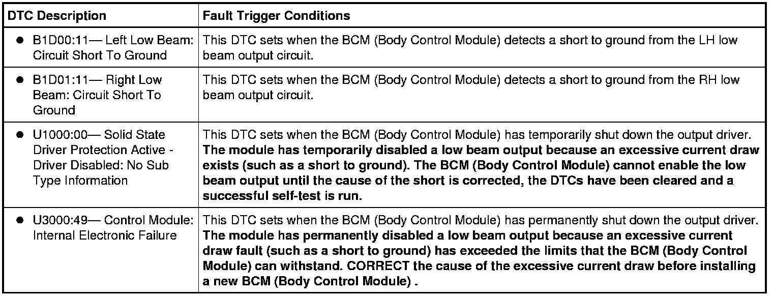
This pinpoint test is intended to diagnose the following:
- Fuse
- Bulb
- Wiring, terminals or connectors
- BCM (Body Control Module)
PINPOINT TEST A : ONE OR BOTH LOW BEAMS ARE INOPERATIVE
NOTICE: Use the correct probe adapter(s) when making measurements. Failure to use the correct probe adapter(s) may damage the connector.
NOTE:
Due to varying wattage ratings and the resulting current draw differences of certain aftermarket headlamp bulbs, the BCM (Body Control Module) may activate its short circuit protection strategy, resulting in the low beam output circuit becoming inoperative. Verify the bulbs meet Ford specifications. If the bulbs do not meet Ford specifications, install the correct bulbs. Run the on-demand self-test (required to clear certain DTCs and reset the BCM (Body Control Module) ). Correct any unresolved DTCs. Clear all DTCs. Test the system for normal operation.
A1 CHECK FOR VOLTAGE TO THE HEADLAMP
- Ignition OFF.
- Disconnect: Inoperative Headlamp.
- Place the headlamp switch in the HEADLAMPS ON position.
- Measure the voltage between the LH headlamp C1021-1, circuit CLF04 (BN/BU), harness side and ground; or between the RH headlamp C1041-1, circuit CLF05 (BU/GN), harness side and ground.

Is the voltage greater than 10 volts?
Yes
REPAIR the circuit GD120 (BK/GN) (LH headlamp) or circuit GD123 (BK/GY) (RH headlamp) for an open. TEST the system for normal operation.
No
VERIFY the BCM (Body Control Module) fuse 17 (10A) (LH low beam) or fuse 16 (10A) (RH low beam) is OK. If OK, GO to A2. If not OK, REFER to the Wiring Diagrams to identify the possible causes of the circuit short [1][2]Diagrams By Number. After the repair:
If no DTCs are present, TEST the system for normal operation.
If DTC U1000:00 is present, CLEAR the DTCs and REPEAT the self-test (required to enable the low beam output driver if DTC U1000:00 is present). TEST the system for normal operation.
If DTC U3000:49 is present, INSTALL a new BCM (Body Control Module). TEST the system for normal operation.
A2 REPEAT THE ON-DEMAND SELF-TEST AND CHECK FOR VOLTAGE TO THE HEADLAMP
- Place the headlamp switch in the OFF position.
- Ignition ON.
- Enter the following diagnostic mode on the scan tool: BCM (Body Control Module) Self-Test.
- Clear the DTCs and repeat the on-demand self-test.
- Place the headlamp switch in the HEADLAMPS ON position.
- Measure the voltage between the LH headlamp C1021-1, circuit CLF04 (BN/BU), harness side and ground; or between the RH headlamp C1041-1, circuit CLF05 (BU/GN), harness side and ground.
Is the voltage greater than 10 volts?
Yes
INSTALL a new headlamp bulb. REFER to Headlamp Bulb . TEST the system for normal operation.
No
GO to A3.
A3 CHECK THE BCM (Body Control Module) LOW BEAM VOLTAGE SUPPLY CIRCUIT FOR A SHORT TO GROUND
- Place the headlamp switch in the OFF position.
- Ignition OFF.
- Disconnect: BCM (Body Control Module) C2280E.
- Measure the resistance between the LH headlamp C1021-1, circuit CLF04 (BN/BU), harness side and ground; or between the RH headlamp C1041-1, circuit CLF05 (BU/GN), harness side and ground.

Is the resistance greater than 10,000 ohms?
Yes
GO to A4.
No
REPAIR circuit CLF04 (BN/BU) (LH headlamp) or circuit CLF05 (BU/GN) (RH headlamp) for a short to ground. After the repair:
If no DTCs are present, TEST the system for normal operation.
If DTC U1000:00 is present, CLEAR the DTCs and REPEAT the self-test (required to enable the low beam output driver if DTC U1000:00 is present). TEST the system for normal operation.
If DTC U3000:49 is present, INSTALL a new BCM (Body Control Module). TEST the system for normal operation.
A4 CHECK THE BCM (Body Control Module) LOW BEAM VOLTAGE SUPPLY CIRCUIT FOR AN OPEN
- Measure the resistance between the LH headlamp C1021-1, circuit CLF04 (BN/BU), harness side and the BCM (Body Control Module) C2280E-2, circuit CLF04 (BN/BU), harness side; or between the RH headlamp C1041-1, circuit CLF05 (BU/GN), harness side and the BCM (Body Control Module) C2280E-1, circuit CLF05 (BU/GN), harness side.
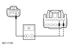
Is the resistance less than 5 ohms?
Yes
GO to A5.
No
REPAIR circuit CLF04 (BN/BU) (LH headlamp) or circuit CLF05 (BU/GN) (RH headlamp) for an open. TEST the system for normal operation.
A5 CHECK FOR CORRECT BCM (Body Control Module) OPERATION
- Disconnect all the BCM (Body Control Module) connectors.
- Check for:
- corrosion
- damaged pins
- pushed-out pins
- Connect all the BCM (Body Control Module) connectors and make sure they seat correctly.
- Operate the system and verify the concern is still present.
Is the concern still present?
Yes
INSTALL a new BCM (Body Control Module). TEST the system for normal operation.
No
The system is operating correctly at this time. The concern may have been caused by a loose or corroded connector.