Pinpoint Test C: Poor Quality Or No Sound From One Or More Speakers (Not All Speakers) - Sony(R) Sound
Information and Entertainment System
Pinpoint Test C: Poor Quality Or No Sound From One Or More Speakers (Not All Speakers) - Sony(R) Sound
Normal Operation
The Audio Front Control Module (ACM) directs audio signals to the audio Digital Signal Processing (DSP) module in the form of an AC voltage. The audio DSP (Digital Signal Processing) module boosts the audio signals and sends them to the speakers. The ACM (Audio Front Control Module) provides internal circuit protection for shorts to ground or shorts to voltage.
A short to ground or short to voltage in the circuitry to the audio amplifier may cause multiple speakers to lose sound due to the built-in overload protection feature of the ACM (Audio Front Control Module). In this case, a speaker fault DTC sets and this pinpoint test should be followed to isolate the damaged circuit.
Use the speaker walk test to isolate a concern with a particular speaker. This reduces the diagnostic steps necessary to isolate the concern. To carry out the speaker walk test, refer to Audio Control Module (ACM) Self-Diagnostic Mode Service and Repair.
Audio DSP (Digital Signal Processing) Module DTCs
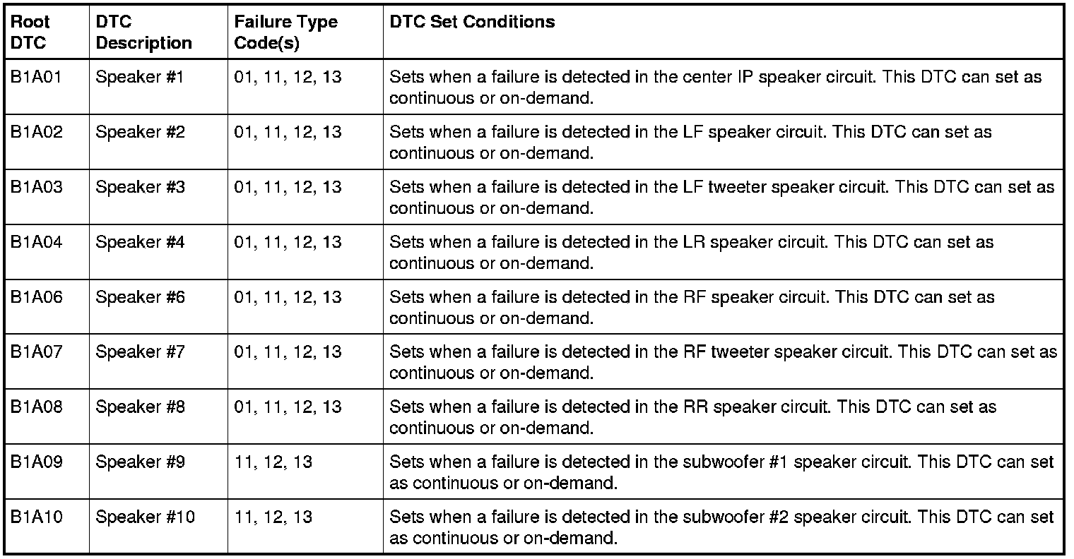
This pinpoint test is intended to diagnose the following:
- Wiring, terminals or connectors
- Speaker
- Audio DSP (Digital Signal Processing) module
- ACM (Audio Front Control Module)
PINPOINT TEST C : POOR QUALITY OR NO SOUND FROM ONE OR MORE SPEAKERS (NOT ALL SPEAKERS) - SONY(R) SOUND
NOTICE: Use the correct probe adapter(s) when making measurements. Failure to use the correct probe adapter(s) may damage the connector.
C1 CHECK THE AUDIO SIGNALS TO THE SUSPECT SPEAKER
- Ignition OFF.
- Disconnect: Suspect Speaker.
- Operate the audio system in radio tuner (AM/FM), single-play mode.
- Measure the AC voltage between the suspect speaker pin 1 and pin 2, harness side as follows:
Suspect Speaker Positive Meter Lead Negative Meter Lead LH front C523-1
VME07 (WH) C523-2
RME07 (WH/BN) RH front C612-1
VME10 (WH/VT) C612-2
RME10 (WH/OG) LH rear C702-1
VME09 (WH/GN) C702-2
RME09 (BN/YE) RH rear C802-1
VME12 (BN/WH) C802-2
RME12 (BN/BU) LH front tweeter C230-1
VME08 (GN/OG) C230-2
RME08 (GY/OG) RH front tweeter C231-1
VME11 (VT/OG) C231-2
RME11 (YE/OG) Instrument panel speaker C2356-1
VME06 (GN) C2356-2
RME06 (GY/YE) Subwoofer #1 C3020-1
CPR41 (BU/WH) C3020-2
CPR42 (WH) Subwoofer #2 C3020-3
VPR43 (GY/BU) C3020-4
RPR47 (BU/GN)
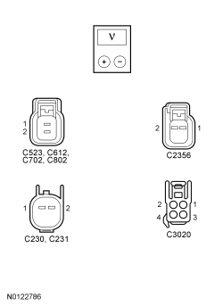
Is a fluctuating AC voltage present?
Yes
INSTALL a new speaker for the suspect speaker. REFER to Speaker - Door , Speaker - Instrument Panel or Speaker - A-Pillar . CLEAR any DTCs present. TEST the system for normal operation.
No
GO to C2.
C2 CHECK THE CIRCUITS TO THE SUSPECT SPEAKER FOR A SHORT TO VOLTAGE
- Ignition OFF.
- Disconnect: Audio DSP (Digital Signal Processing) Module C3154B or C3154C.
- Ignition ON.
- Measure the voltage between the suspect speaker pins, harness side and ground as follows:
Suspect Speaker Positive Meter Lead Negative Meter Lead LH front C523-1
VME07 (WH) Ground C523-2
RME07 (WH/BN) Ground RH front C612-1
VME10 (WH/VT) Ground C612-2
RME10 (WH/OG) Ground LH rear C702-1
VME09 (WH/GN) Ground C702-2
RME09 (BN/YE) Ground RH rear C802-1
VME12 (BN/WH) Ground C802-2
RME12 (BN/BU) Ground LH front tweeter C230-1
VME08 (GN/OG) Ground C230-2
RME08 (GY/OG) Ground RH front tweeter C231-1
VME11 (VT/OG) Ground C231-2
RME11 (YE/OG) Ground Instrument panel speaker C2356-1
VME06 (GN) Ground C2356-2
RME06 (GY/YE) Ground Subwoofer #1 C3020-1
CPR41 (BU/WH) Ground C3020-2
CPR42 (WH) Ground Subwoofer #2 C3020-3
VPR43 (GY/BU) Ground C3020-4
RPR47 (BU/GN) Ground
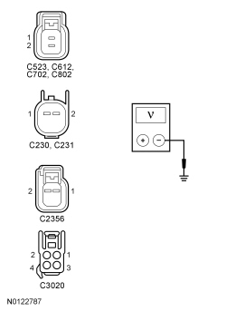
Is any voltage present?
Yes
REPAIR the circuit in question. CLEAR any DTCs present. TEST the system for normal operation.
No
GO to C3.
C3 CHECK THE CIRCUITS TO THE SUSPECT SPEAKER FOR AN OPEN OR SHORT TO GROUND
- Ignition OFF.
- Measure the resistance between the suspect speaker, harness side and the audio DSP (Digital Signal Processing) module, harness side; and between the suspect speaker, harness side and ground as follows:
Suspect Speaker Positive Meter Lead Negative Meter Lead Circuit LH front C523-1 C3154B-2 VME07 (WH) C523-2 C3154B-10 RME07 (WH/BN) RH front C612-1 C3154B-6 VME10 (WH/VT) C612-2 C3154B-14 RME10 (WH/OG) LH rear C702-1 C3154B-4 VME09 (WH/GN) C702-2 C3154B-12 RME09 (BN/YE) RH rear C802-1 C3154B-8 VME12 (BN/WH) C802-2 C3154B-16 RME12 (BN/BU) LH front tweeter (Premium audio) C230-1 C3154B-3 VME08 (GN/OG) C230-2 C3154B-11 RME08 (GY/OG) RH front tweeter (Premium audio) C231-1 C3154B-7 VME11 (VT/OG) C231-2 C3154B-15 RME11 (YE/OG) Instrument panel speaker C2356-1 C3154B-1 VME06 (GN) C2356-2 C3154B-9 RME06 (GY/YE) Subwoofer #1 C3020-1 C3154C-1 CPR41 (BU/WH) C3020-2 C3154C-9 CPR42 (WH) Subwoofer #2 C3020-3 C3154C-2 VPR43 (GY/BU) C3020-4 C3154C-10 RPR47 (BU/GN)
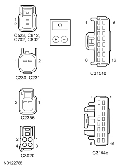
Is the resistance less than 5 ohms between the suspect speaker and the ACM (Audio Front Control Module) and greater than 10,000 ohms between the suspect speaker and ground?
Yes
REPAIR the circuit in question. CLEAR any DTCs present. TEST the system for normal operation.
No
GO to C4.
C4 CHECK THE AUDIO DSP (Digital Signal Processing) MODULE VOLTAGE SUPPLY
- Ignition OFF.
- Disconnect: Audio DSP (Digital Signal Processing) Module C3154C.
- Measure the voltage between the audio DSP (Digital Signal Processing) module, harness side and ground as follows:
Positive Meter Lead Negative Meter Lead C3154C-5
SBP19 (BU/RD) Ground C3154C-6
SBP19 (BU/RD) Ground
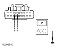
Are the voltages greater than 10 volts?
Yes
GO to C5.
No
VERIFY the Body Control Module (BCM) fuse 19 (20A) is OK. If OK, REPAIR the circuit in question. TEST the system for normal operation. If not OK, REFER to the Wiring Diagrams to identify the possible causes of the circuit short [1][2]Diagrams By Number.
C5 CHECK THE AUDIO DSP (Digital Signal Processing) MODULE GROUND CIRCUITS FOR CONTINUITY
- Ignition OFF.
- Disconnect: Negative Battery Cable.
- Measure the resistance between the audio DSP (Digital Signal Processing) module, harness side and ground as follows:
Positive Meter Lead Negative Meter Lead C3154C-15
GD148 (BK/YE) Ground C3154C-16
GD148 (BK/YE) Ground
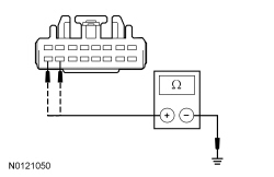
Are the resistances less than 5 ohms?
Yes
CONNECT the negative battery cable. GO to C6.
No
REPAIR the circuit in question. TEST the system for normal operation.
C6 CHECK FOR AN AUDIO SIGNAL AT THE AUDIO DSP (Digital Signal Processing) MODULE
- Connect: Audio DSP (Digital Signal Processing) Module C3154B.
- Connect: Audio DSP (Digital Signal Processing) Module C3154C.
- Disconnect: Audio DSP (Digital Signal Processing) Module C3154A.
- Operate the audio system in radio tuner (AM/FM) mode.
- Measure the AC voltage between the audio amplifier pins, harness side as follows:
Circuit Positive Meter Lead Negative Meter Lead LH C3154A-7
VME17 (GN) C3154A-17
RME17 (GY) RH C3154A-9
VME18 (VT) C3154A-19
RME18 (YE)
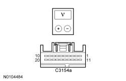
Is a fluctuating AC voltage present?
Yes
GO to C10.
No
GO to C7.
C7 CHECK THE AUDIO CIRCUITS TO THE AUDIO DSP (Digital Signal Processing) MODULE FOR A SHORT TO VOLTAGE
- Ignition OFF.
- Disconnect: ACM (Audio Front Control Module) C290A.
- Disconnect: Audio DSP (Digital Signal Processing) Module C3154A.
- Ignition ON.
- Measure the voltage between the audio DSP (Digital Signal Processing) module pins, harness side and ground as follows:
Circuit Positive Meter Lead Negative Meter Lead LH C3154A-7
VME17 (GN) Ground C3154A-17
RME17 (GY) Ground RH C3154A-9
VME18 (VT) Ground C3154A-19
RME18 (YE) Ground
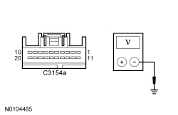
Is any voltage present?
Yes
REPAIR the circuit in question. CLEAR any DTCs present. TEST the system for normal operation.
No
GO to C8.
C8 CHECK THE AUDIO CIRCUITS TO THE AUDIO DSP (Digital Signal Processing) MODULE FOR AN OPEN OR SHORT TO GROUND
- Ignition OFF.
- Measure the resistance between the audio DSP (Digital Signal Processing) module, harness side and the ACM (Audio Front Control Module), harness side; and between the audio DSP (Digital Signal Processing) module, harness side and ground as follows:
Suspect Speaker Positive Meter Lead Negative Meter Lead Circuit LH C3154A-7 C290A-8, then ground VME17 (GN) C3154A-17 C290A-21, then ground RME17 (GY) RH C3154A-9 C290A-11, then ground VME18 (VT) C3154A-19 C290A-12, then ground RME18 (YE)
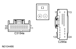
Are the resistances less than 5 ohms between the audio DSP (Digital Signal Processing) module and the ACM (Audio Front Control Module) and greater than 10,000 ohms between the audio DSP (Digital Signal Processing) module and ground?
Yes
GO to C9.
No
REPAIR the circuit in question. CLEAR any DTCs present. TEST the system for normal operation.
C9 CHECK FOR CORRECT ACM (Audio Front Control Module) OPERATION
- Ignition OFF.
- Connect: All Disconnected Connectors.
- Disconnect all the ACM (Audio Front Control Module) connectors.
- Check for:
- corrosion
- damaged pins
- pushed-out pins
- Connect all the ACM (Audio Front Control Module) connectors and make sure they seat correctly.
- Operate the system and determine if the concern is still present.
Is the concern still present?
Yes
INSTALL a new ACM (Audio Front Control Module). REFER to Audio Control Module (ACM) . TEST the system for normal operation.
No
The system is operating correctly at this time. The concern may have been caused by a loose or corroded connector. CLEAR any DTCs present.
C10 CHECK FOR CORRECT AUDIO DSP (Digital Signal Processing) MODULE OPERATION
- Ignition OFF.
- Connect: All Disconnected Connectors.
- Disconnect all the audio DSP (Digital Signal Processing) module connectors.
- Check for:
- corrosion
- damaged pins
- pushed-out pins
- Connect all the audio DSP (Digital Signal Processing) module connectors and make sure they seat correctly.
- Operate the system and determine if the concern is still present.
Is the concern still present?
Yes
INSTALL a new audio DSP (Digital Signal Processing) module. REFER to Audio Digital Signal Processing (DSP) Module - Front Captain's Chair or Audio Digital Signal Processing (DSP) Module - Split Bench . TEST the system for normal operation.
No
The system is operating correctly at this time. The concern may have been caused by a loose or corroded connector. CLEAR any DTCs present.