Upper Intake Manifold: Installation
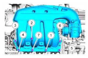
- Using a new gasket, install the intake manifold and the 7 bolts and tighten in the sequence shown in illustration in 2 stages.
- Stage 1: Tighten to 10 Nm (89 lb-in).
- Stage 2: Tighten an additional 45 degrees.
 Courtesy of FORD MOTOR CO.
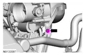
- Install the upper intake manifold support bolt.
- Tighten to 10 Nm (89 lb-in).
 Courtesy of FORD MOTOR CO.
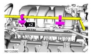
- Attach the 2 coolant tube retainers to the upper intake manifold.
 Courtesy of FORD MOTOR CO.
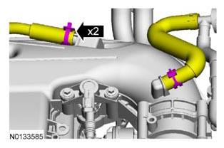
- Connect the power brake booster vacuum supply hose and crankcase ventilation hose to the upper intake manifold.
 Courtesy of FORD MOTOR CO.
- Connect the EVAP vapor tube to the EVAP canister purge valve. REFER to QUICK CONNECT COUPLING
.
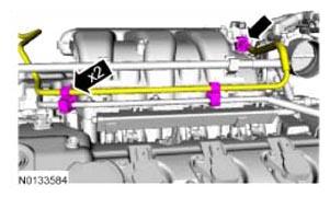
- Attach the EVAP vapor tube to the 2 retainers.
 Courtesy of FORD MOTOR CO.
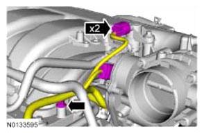
- Connect the EVAP canister purge valve and throttle body electrical connectors.
- Attach the wiring harness pin-type retainer to the upper intake manifold.
 Courtesy of FORD MOTOR CO.
- Install the ACL outlet pipe. REFER to INTAKE AIR SYSTEM COMPONENTS - EXPLODED VIEW
.