Charge Air Cooler (CAC) System
The CAC system cools the intake air which has been heated by the turbocharger. The removal of heat from the pressurized air going into the CAC increases the air density which improves combustion efficiency, engine horsepower, and torque. The system consists of a CAC radiator in the grille and tubing to interconnect these components. The CAC is positioned after the turbocharger directly in the flow of the intake air. As the heated air flows through the CAC, it is cooled by the airflow through the grille. The PCM maintains a desirable intake air temperature by monitoring the TCBP/CACT (located at the throttle body) and the MAP/IAT2 (located at the intake manifold) sensors.
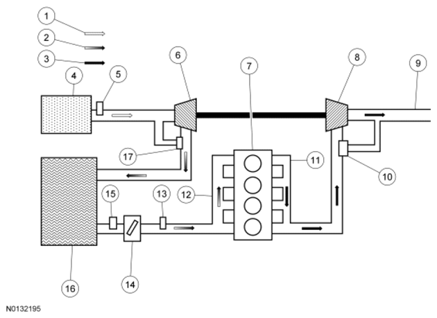 Courtesy of FORD MOTOR CO.
| Turbocharger System |
Component |
| 1 |
Intake Air |
| 2 |
Compressed Air |
| 3 |
Exhaust Air |
| 4 |
Air Filter |
| 5 |
MAF/IAT Sensor (MAF Not Used) |
| 6 |
Turbocharger Intake Compressor |
| 7 |
Cylinder Head |
| 8 |
Turbocharger Exhaust Turbine |
| 9 |
Outlet To Exhaust System |
| 10 |
Turbocharger Wastegate |
| 11 |
Exhaust Manifold |
| 12 |
Intake Manifold |
| 13 |
MAP Sensor |
| 14 |
Intake Throttle Assembly |
| 15 |
Turbocharger Boost Pressure/Charger Air Cooler Temperature (TCBP/CACT) Sensor |
| 16 |
CAC |
| 17 |
Turbocharger Bypass Valve |
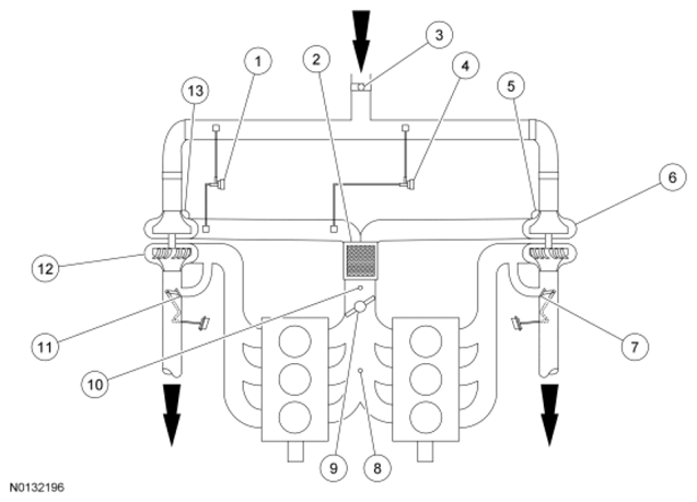 Courtesy of FORD MOTOR CO.
| Turbocharger System |
Component |
| 1 |
Turbocharger Bypass Valve Left Bank (Bank 2) (If Equipped) |
| 2 |
Charge Air Cooler (CAC) |
| 3 |
Turbocharger Intake Pressure And Temperature (TCIPT) Sensor (If Equipped) |
| 4 |
Turbocharger Bypass Valve Right Bank (Bank 1) (If Equipped) |
| 5 |
Turbocharger Bypass Valve Right Bank (Bank 1) (Integrated In Turbocharger) (If Equipped) |
| 6 |
Turbocharger Right Bank (Bank 1) |
| 7 |
Wastegate Right Bank (Bank 1) |
| 8 |
Manifold Absolute Pressure/Intake Air Temperature 2 (MAP/IAT2) Sensor |
| 9 |
Throttle Body |
| 10 |
Turbocharger Boost Pressure/Charger Air Cooler Temperature (TCBP/CACT) Sensor |
| 11 |
Wastegate Left Bank (Bank 2) |
| 12 |
Turbocharger Left Bank (Bank 2) |
| 13 |
Turbocharger Bypass Valve Left Bank (Bank 2) (Integrated In Turbocharger) (If Equipped) |