Pinpoint Test AN: The Chime Sounds When The Driver Door Is Ajar (No Key In Ignition And Headlamps Off)
Instrumentation, Message Center and Warning Chimes
Pinpoint Test AN: The Chime Sounds When The Driver Door Is Ajar (No Key In Ignition And Headlamps Off)
Refer to Wiring Diagram Set 60, Instrument Cluster for schematic and connector information Electrical Diagrams.
Normal Operation
When the key is inserted into the ignition lock cylinder, the key-in-ignition switch (part of the ignition switch) closes, providing a voltage signal to the Smart Junction Box (SJB). The key-in-ignition voltage is also provided to the remote start system if equipped. The key-in-ignition and door ajar status is communicated to the IC (Instrument Cluster) from the SJB (Smart Junction Box) over the Medium Speed Controller Area Network (MS-CAN) communication bus. If the IC (Instrument Cluster) detects that the ignition switch is in the OFF or ACC position and the SJB (Smart Junction Box) communicates to the IC (Instrument Cluster) that the driver door is ajar and the key is in the ignition, the key-in-ignition warning chime sounds. The SJB (Smart Junction Box) also communicates to the IC (Instrument Cluster) that the headlamps or parking lamps are on and the driver door is opened for the headlamps on warning chime. The headlamps on warning chime sounds when the driver door is opened with the ignition switch in the OFF position, the key is not in the ignition lock cylinder, and the headlamp switch is in the PARK or HEADLAMP ON position.
- DTC B1352 (Ignition Key-In Circuit Failure)- an on-demand DTC that sets if the SJB (Smart Junction Box) detects an open or short to ground on the key-in-ignition switch input circuit or if the SJB (Smart Junction Box) detects ignition START, RUN/START or RUN/ACC inputs without the key-in-ignition input.
This pinpoint test is intended to diagnose the following:
- Wiring, terminals or connectors
- Ignition switch
- SJB (Smart Junction Box)
PINPOINT TEST AN : THE CHIME SOUNDS WHEN THE DRIVER DOOR IS AJAR (NO KEY IN IGNITION AND HEADLAMPS OFF)
NOTICE: Use the correct probe adapter(s) when making measurements. Failure to use the correct probe adapter(s) may damage the connector.
AN1 CHECK THE IC (Instrument Cluster) ILLUMINATION
- Verify the IC (Instrument Cluster) is not illuminated with the headlamp switch off.
Does the IC (Instrument Cluster) illumination operate correctly?
Yes
GO to AN2.
No
REFER to Instrument Panel, Gauges and Warning Indicators.
AN2 RETRIEVE THE RECORDED DTCs FROM THE SJB (Smart Junction Box) SELF-TEST
- Check the recorded DTCs from the SJB (Smart Junction Box) self-test.
Are any DTCs present?
Yes
For DTC B1352, GO to AN3.
For all other DTCs, REFER to Body Control Systems.
No
If equipped with the remote start system, GO to AN4.
If not equipped with the remote start system, GO to AN5.
AN3 CHECK THE SJB (Smart Junction Box) INPUT PIDs FROM THE IGNITION SWITCH
- Enter the following diagnostic mode on the scan tool: SJB (Smart Junction Box) DataLogger.
- Select and monitor the SJB (Smart Junction Box) PIDs ignition switch ACC (IGN_A_ECU), OFF (IGN_O_ECU), RUN (IGN_R_ECU) and START (IGN_S_ECU) while cycling the ignition switch from ACC, OFF, RUN and START.
Do the SJB (Smart Junction Box) PIDs match the ignition switch positions?
Yes
GO to AN7.
No
REFER to Steering Column to diagnose the ignition switch outputs to the SJB (Smart Junction Box).
AN4 CHECK THE REMOTE START SYSTEM
- Ignition OFF.
- Disconnect: Remote Start System Module.
Does the chime stop sounding?
Yes
REPAIR the remote start system.
No
GO to AN5.
AN5 CHECK THE KEY-IN-IGNITION INPUT CIRCUIT FOR VOLTAGE
- Ignition OFF.
- Disconnect: SJB (Smart Junction Box) C2280B.
- Remove the key from the ignition lock cylinder.
- Measure the voltage between the SJB (Smart Junction Box) C2280B-35, circuit CDC30 (BU/GY), harness side and ground.
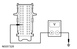
Is any voltage present?
Yes
GO to AN6.
No
GO to AN7.
AN6 CHECK KEY-IN-IGNITION INPUT CIRCUIT FOR A SHORT TO VOLTAGE
- Disconnect: Ignition Switch C250.
- Measure the voltage between the SJB (Smart Junction Box) C2280B-35, circuit CDC30 (BU/GY), harness side and ground.
Is any voltage present?
Yes
REPAIR circuit CDC30 (BU/GY) for a short to voltage. TEST the system for normal operation.
No
INSTALL a new ignition switch. TEST the system for normal operation.
AN7 CHECK FOR CORRECT SJB (Smart Junction Box) OPERATION
- Disconnect all the SJB (Smart Junction Box) connectors.
- Check for:
- corrosion
- damaged pins
- pushed-out pins
- Connect all the SJB (Smart Junction Box) connectors and make sure they seat correctly.
- Operate the system and verify the concern is still present.
Is the concern still present?
Yes
INSTALL a new SJB (Smart Junction Box). TEST the system for normal operation.
No
The system is operating correctly at this time. The concern may have been caused by a loose or corroded connector.