Pinpoint Test D: Poor Quality/Distorted/No Sound From One Or More Speakers (Not All Speakers) - Expedition With Navigation
Information and Entertainment System
Pinpoint Test D: Poor Quality/Distorted/No Sound From One Or More Speakers (Not All Speakers) - Expedition With Navigation
Refer to Wiring Diagram Set 130, Audio System/Navigation for schematic and connector information Electrical Diagrams.
Normal Operation
The Audio Front Control Module (ACM) directs the front speaker audio signals to the audio amplifier in the form of an AC voltage. The amplifier boosts the audio signals and sends them to the speakers. The ACM (Audio Front Control Module) provides internal circuit protection for shorts to ground or shorts to voltage.
The rear channel audio signals from the ACM (Audio Front Control Module) route to the audio RCU (Rear Control Unit) module and the audio amplifier. The audio amplifier sends the audio signals to the rear speakers. In dual-play mode, the the audio amplifier mutes the rear speaker output. Make sure the audio system is in single-play mode before diagnosing a rear speaker concern.
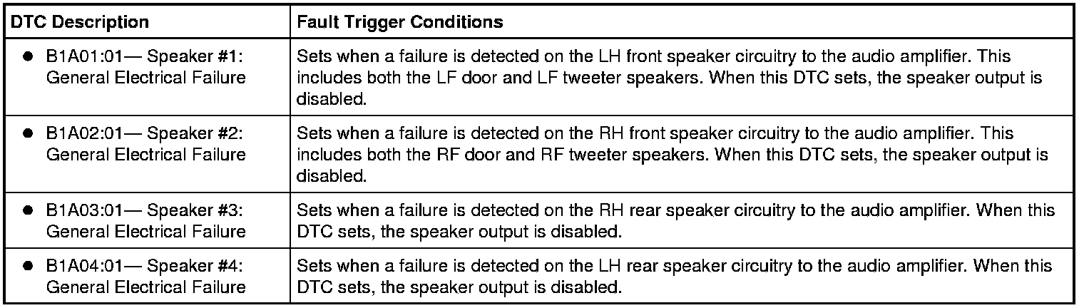
A short to ground or short to voltage in the circuitry to one of the speakers may cause multiple speakers to lose sound due to the built-in overload protection feature of the ACM (Audio Front Control Module). In this case, a speaker fault DTC sets, and this pinpoint test should be followed to isolate the damaged circuit.
It should also be noted that when the ACM (Audio Front Control Module) activates the built-in overload protection, DTC B1342 may also be set. The circuit failure must be repaired before DTC B1342 can be cleared.
To enable the audio amplifier, the ACM (Audio Front Control Module) sends voltage through the enable/clip circuit. The circuit acts as both an output (to enable the amplifier) and an input (to detect an amplifier overload condition). The voltage sent by the ACM (Audio Front Control Module) passes through a variable resistor in the audio amplifier, then to ground. As the amplifier reaches maximum output, the resistance in the variable resistor decreases. This decreases the voltage drop, resulting in the ACM (Audio Front Control Module) detecting a higher voltage on the enable/clip circuit. When the voltage reaches the clip threshold, the ACM (Audio Front Control Module) clips the audio output signal to the amplifier (heard as distortion), in order to prevent damage to the amplifier and speakers.
The enable/clip status is based on the following voltages, as detected by the ACM (Audio Front Control Module) :
- Less then 0.4 volt: amplifier disabled
- Between 3.8 and 6.7 volts: amplifier enabled
- Greater than 8.5 volts: amplifier clipped
An open in the enable/clip circuit causes the speakers to produce no sound because the enable signal does not reach the audio amplifier. A short to ground or short to voltage can cause severe distortion to be heard in the speakers. In either of these scenarios, the subwoofer should continue to operate correctly, as it utilizes a separate amplifier and enable/clip circuit.
For vehicles with navigation, it is also important to note that if the navigation voice guidance setting is set too low, it may appear that the front speakers intermittently produce no sound. Make sure the voice guidance setting is set high enough to hear the voice guidance commands before addressing a concern with the front speakers.
The speaker walk test can be used to isolate a concern with a particular speaker. This can reduce the diagnostic steps necessary to isolate the concern. To carry out the speaker walk test, refer to Audio Control Module (ACM) Self-Diagnostic Mode Service and Repair.
This pinpoint test is intended to diagnose the following:
- Fuse
- Wiring, terminals or connectors
- Speaker
- Audio amplifier
- Audio RCU (Rear Control Unit) module (if equipped)
- ACM (Audio Front Control Module)
PINPOINT TEST D : POOR QUALITY/DISTORTED/NO SOUND FROM ONE OR MORE SPEAKERS (NOT ALL SPEAKERS) - EXPEDITION WITH NAVIGATION
NOTICE: Use the correct probe adapter(s) when making measurements. Failure to use the correct probe adapter(s) may damage the connector.
NOTE: Failure to disconnect the battery when instructed will result in false resistance readings.
D1 DETERMINE THE INOPERATIVE SPEAKER(S)
- Carry out the speaker walk test. Refer to Audio Control Module (ACM) Self-Diagnostic Mode Service and Repair.
Is the concern with the subwoofer speaker?
Yes
GO to Pinpoint Test H. Pinpoint Test H: The Subwoofer is Inoperative/Does Not Operate Correctly
No
If the concern is with a tweeter speaker only, GO to D2.
For all other concerns, GO to D5.
D2 CHECK THE AUDIO SIGNALS TO THE SUSPECT TWEETER SPEAKER
- Ignition OFF.
- Disconnect: Suspect Tweeter Speaker.
- Operate the audio system in radio tuner (AM/FM) mode.
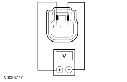
- Measure the AC voltage between the suspect tweeter speaker pin 1 and pin 2, harness side as follows:
Suspect Speaker Positive Meter Lead Negative Meter Lead LH tweeter C513-1 VME08 (GN/OG) C513-2 RME08 (GY/OG) RH tweeter C613-1 VME11 (VT/OG) C613-2 RME11 (YE/OG)
Is a fluctuating AC voltage present?
Yes
INSTALL a new speaker for the suspect tweeter speaker. REFER to Speaker - Door . TEST the system for normal operation.
No
GO to D3.
D3 CHECK THE CIRCUITS TO THE SUSPECT TWEETER SPEAKER FOR A SHORT TO VOLTAGE
- Ignition OFF.
- Disconnect: LF Door Speaker C523B (LH Speaker Concern) or RF Door Speaker C612B (RH Speaker Concern).
- Ignition ON.
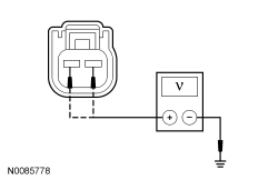
- Measure the voltage between the suspect tweeter speaker, harness side and ground as follows:
Suspect Tweeter Speaker Positive Meter Lead Negative Meter Lead LH tweeter C513-1 VME08 (GN/OG) Ground C513-2 RME08 (GY/OG) Ground RH tweeter C613-1 VME11 (VT/OG) Ground C613-2 RME11 (YE/OG) Ground
Is any voltage present?
Yes
REPAIR the circuit in question. TEST the system for normal operation.
No
GO to D4.
D4 CHECK THE CIRCUITS TO THE SUSPECT TWEETER SPEAKER FOR AN OPEN OR SHORT TO GROUND
- Ignition OFF.
- Measure the resistance between the suspect tweeter speaker, harness side and the respective door speaker, harness side; and between the suspect tweeter speaker, harness side and ground as follows:
Suspect Tweeter Speaker Positive Meter Lead Negative Meter Lead Circuit LH tweeter C513-1 C523B-1, then ground VME08 (GN/OG) C513-2 C523B-2, then ground RME08 (GY/OG) RH tweeter C613-1 C612B-1, then ground VME11 (VT/OG) C613-2 C612B-2, then ground RME11 (YE/OG)
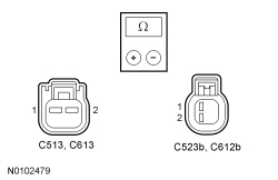
Is the resistance less than 5 ohms between the suspect tweeter speaker and the door speaker, and greater than 10,000 ohms between the suspect tweeter speaker and ground?
Yes
INSTALL a new door speaker. REFER to Speaker - Door . TEST the system for normal operation.
No
REPAIR the circuit in question. TEST the system for normal operation.
D5 CHECK THE AUDIO SIGNALS TO THE SUSPECT SPEAKER
- Ignition OFF.
- Disconnect: Suspect Speaker.
- Operate the audio system in radio tuner (AM/FM), single-play mode.
- Measure the AC voltage between the suspect speaker pins, harness side as follows:
Suspect Speaker Positive Meter Lead Negative Meter Lead LF door C523A-1 VME07 (WH) C523A-2 RME07 (WH/BN) RF door C612A-1 VME10 (WH/VT) C612A-2 RME10 (WH/OG) LR door C702-1 VME12 (BN/WH) C702-2 RME12 (BN/BU) RR door C802-1 VME12 (BN/WH) C802-2 RME12 (BN/BU)

Is a fluctuating AC voltage present?
Yes
INSTALL a new speaker for the suspect speaker. REFER to Speaker - Door . TEST the system for normal operation.
No
GO to D6.
D6 CHECK THE AUDIO SIGNALS TO THE AUDIO AMPLIFIER
- Ignition OFF.
- Disconnect: Audio Amplifier C2385A.
- Operate the audio system in radio tuner (AM/FM), single-play mode.
- Measure the AC voltage between the audio amplifier pins, harness side as follows:
Suspect Speaker Positive Meter Lead Negative Meter Lead LF (door and tweeter) C2385A-8 VME07 (WH) C2385A-4 RME07 (WH/BN) RF (door and tweeter) C2385A-6 VME10 (WH/VT) C2385A-2 RME10 (WH/OG) LR (door) C2385A-7 VME09 (WH/GN) C2385A-3 RME09 (BN/YE) RR (door) C2385A-5 VME12 (BN/WH) C2385A-1 RME12 (BN/BU)
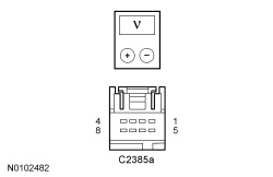
Is a fluctuating AC voltage present?
Yes
GO to D9.
No
GO to D7.
D7 CHECK THE AUDIO CIRCUITS TO THE AUDIO AMPLIFIER FOR A SHORT TO VOLTAGE
- Ignition OFF.
- Disconnect: ACM (Audio Front Control Module) C240A.
- Ignition ON.
- Measure the voltage between the audio amplifier, harness side and ground as follows:
Suspect Speaker Positive Meter Lead Negative Meter Lead LF (door and tweeter) C2385A-8 VME07 (WH) Ground C2385A-4 RME07 (WH/BN) Ground RF (door and tweeter) C2385A-6 VME10 (WH/VT) Ground C2385A-2 RME10 (WH/OG) Ground LR door C2385A-7 VME09 (WH/GN) Ground C2385A-3 RME09 (BN/YE) Ground RR door C2385A-5 VME12 (BN/WH) Ground C2385A-1 RME12 (BN/BU) Ground
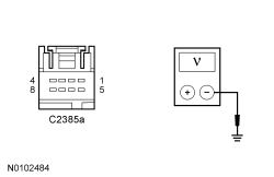
Is any voltage present?
Yes
REPAIR the circuit in question. CLEAR any DTCs present. TEST the system for normal operation.
No
GO to D8.
D8 CHECK THE AUDIO CIRCUITS TO THE AUDIO AMPLIFIER FOR AN OPEN OR SHORT TO GROUND
- Ignition OFF.
- Measure the resistance between the audio amplifier, harness side and the ACM (Audio Front Control Module), harness side; and between the audio amplifier, harness side and ground as follows:
Positive Meter Lead Negative Meter Lead Circuit C2385A-5 C240A-10, then ground VME12 (BN/WH) C2385A-1 C240A-23, then ground RME12 (BN/BU) C2385A-7 C240A-9, then ground VME09 (WH/GN) C2385A-3 C240A-22, then ground RME09 (BN/YE) C2385A-8 C240A-8, then ground VME07 (WH) C2385A-4 C240A-21, then ground RME07 (WH/BN) C2385A-6 C240A-11, then ground VME10 (WH/VT) C2385A-2 C240A-12, then ground RME10 (WH/OG)
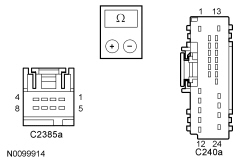
Are the resistances less than 5 ohms between the audio amplifier and the ACM (Audio Front Control Module), and greater than 10,000 ohms between the audio amplifier and ground?
Yes
GO to D18.
No
REPAIR the circuit in question. CLEAR any DTCs present. TEST the system for normal operation.
D9 CHECK THE AUDIO AMPLIFIER ENABLE CIRCUIT VOLTAGE
- Ignition OFF.
- Disconnect: Audio Amplifier C2385B.
- Operate the audio system in radio tuner (AM/FM), single-play mode.
- Measure the voltage between the audio amplifier C2385B-9, circuit CME27 (YE/VT), harness side and ground.
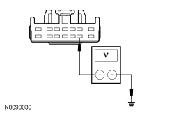
Is the voltage between 3.8 and 6.7 volts?
Yes
GO to D12.
No
GO to D10.
D10 CHECK THE AUDIO AMPLIFIER ENABLE CIRCUIT FOR A SHORT TO VOLTAGE
- Ignition OFF.
- Disconnect: ACM (Audio Front Control Module) C240A.
- Ignition ON.
- Measure the voltage between the audio amplifier C2385B-9, circuit CME27 (YE/VT), harness side and ground.
Is any voltage present?
Yes
REPAIR the circuit. TEST the system for normal operation.
No
GO to D11.
D11 CHECK THE AUDIO AMPLIFIER ENABLE CIRCUIT FOR AN OPEN OR SHORT TO GROUND
- Ignition OFF.
- Measure the resistance between the audio amplifier C2385B-9, circuit CME27 (YE/VT), harness side and the ACM (Audio Front Control Module) C240A-7, circuit CME27 (YE/VT), harness side; and between the audio amplifier C2385B-9, circuit CME27 (YE/VT), harness side and ground.
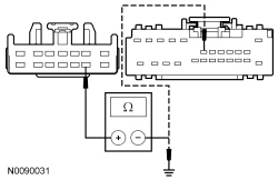
Is the resistance less than 5 ohms between the audio amplifier and the ACM (Audio Front Control Module), and greater than 10,000 ohms between the audio amplifier and ground?
Yes
GO to D19.
No
REPAIR the circuit. TEST the system for normal operation.
D12 CHECK THE SPEAKER CIRCUITS FOR A SHORT TO VOLTAGE
- Ignition OFF.
- Disconnect: Suspect Speaker.
- Measure the voltage between the suspect speaker, harness side and ground as follows:
Suspect Speaker Positive Meter Lead Negative Meter Lead LF door C523A-1 VME07 (WH) Ground C523A-2 RME07 (WH/BN) Ground RF door C612A-1 VME10 (WH/VT) Ground C612A-2 RME10 (WH/OG) Ground LR door C702-1 VME12 (BN/WH) Ground C702-2 RME12 (BN/BU) Ground RR door C802-1 VME12 (BN/WH) Ground C802-2 RME12 (BN/BU) Ground

Is any voltage present?
Yes
REPAIR the circuit in question. TEST the system for normal operation.
No
For front speaker concern, GO to D13.
For rear speaker concern, GO to D14.
D13 CHECK THE FRONT SPEAKER CIRCUITS FOR AN OPEN OR SHORT TO GROUND
- Ignition OFF.
- Measure the resistance between the suspect speaker, harness side and the audio amplifier, harness side; and between the suspect speaker, harness side and ground as follows:
Suspect Speaker Positive Meter Lead Negative Meter Lead Circuit LF door C523A-1, then ground C2385B-13 VME07 (WH) C523A-2, then ground C2385B-6 RME07 (WH/BN) RF door C612A-1, then ground C2385B-11 VME10 (WH/VT) C612A-2, then ground C2385B-4 RME10 (WH/OG)
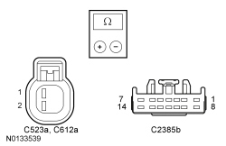
Are the resistances less than 5 ohms between the suspect speaker and the audio amplifier, and greater than 10,000 ohms between the suspect speaker and ground?
Yes
INSTALL a new audio amplifier. REFER to Audio Amplifier . TEST the system for normal operation.
No
REPAIR the circuit in question. TEST the system for normal operation.
D14 CHECK THE REAR AUDIO SIGNALS TO THE AUDIO RCU (Rear Control Unit) MODULE
- Ignition OFF.
- Connect: Audio Amplifier C2385B.
- Disconnect: Audio RCU (Rear Control Unit) Module C3077.
- Operate the audio system in radio tuner (AM/FM), single-play mode.
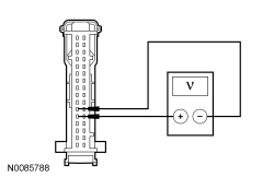
- Measure the AC voltage between the audio RCU (Rear Control Unit) module C3077-11, circuit VME12 (BN/WH), harness side and the audio RCU (Rear Control Unit) module C3077-12, circuit RME12 (BN/BU), harness side.
- Measure the AC voltage between the audio RCU (Rear Control Unit) module C3077-27, circuit VME09 (WH/GN), harness side and the audio RCU (Rear Control Unit) module C3077-28, circuit RME09 (BN/YE), harness side.
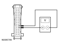
Is a fluctuating AC voltage present?
Yes
GO to D15.
No
GO to D16.
D15 CHECK THE REAR SPEAKER CIRCUITS FOR AN OPEN OR SHORT TO GROUND
- Ignition OFF.
- Measure the resistance between the suspect speaker, harness side and the audio RCU (Rear Control Unit) module, harness side; and between the suspect speaker, harness side and ground as follows:
Suspect Speaker Positive Meter Lead Negative Meter Lead Circuit LR door C702-1, then ground C3077-30 VME09 (WH/GN)/ VME12 (BN/WH) C702-2, then ground C3077-29 RME09 (BN/YE)/ RME12 (BN/BU) RR door C802-1, then ground C3077-14 VME12 (BN/WH) C802-2, then ground C3077-13 RME12 (BN/BU)
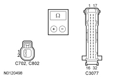
Are the resistances less than 5 ohms between the suspect speaker and the audio RCU (Rear Control Unit) module, and greater than 10,000 ohms between the suspect speaker and ground?
Yes
GO to D19.
No
REPAIR the circuit in question. TEST the system for normal operation.
D16 CHECK THE REAR AUDIO CIRCUITS TO THE AUDIO RCU (Rear Control Unit) MODULE FOR A SHORT TO VOLTAGE
- Ignition OFF.
- Disconnect: Audio Amplifier C2385B.
- Ignition ON.
- Measure the voltage between the audio RCU (Rear Control Unit) module, harness side and ground as follows:
Suspect Speaker Positive Meter Lead Negative Meter Lead LR door C3077-27 VME09 (WH/GN) Ground C3077-28 RME09 (BN/YE) Ground RR door C3077-11 VME12 (BN/WH) Ground C3077-12 RME12 (BN/BU) Ground
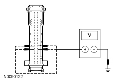
Is any voltage present?
Yes
REPAIR the circuit in question. CLEAR any DTCs present. TEST the system for normal operation.
No
GO to D17.
D17 CHECK THE REAR AUDIO CIRCUITS TO THE AUDIO RCU (Rear Control Unit) MODULE FOR AN OPEN OR SHORT TO GROUND
- Ignition OFF.
- Measure the resistance between the audio amplifier, harness side and the audio RCU (Rear Control Unit) module, harness side; and between the audio amplifier, harness side and ground as follows:
Suspect Speaker Positive Meter Lead Negative Meter Lead Circuit LR door C2385B-12 C3077-27, then ground VME09 (WH/GN) C2385B-5 C3077-28, then ground RME09 (BN/YE) RR door C2385B-10 C3077-11, then ground VME12 (BN/WH) C2385B-3 C3077-12, then ground RME12 (BN/BU)
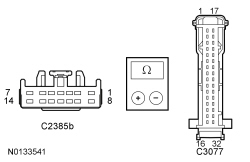
Are the resistances less than 5 ohms between the audio amplifier and the audio RCU (Rear Control Unit) module, and greater than 10,000 ohms between the audio amplifier and ground?
Yes
INSTALL a new audio amplifier. REFER to Audio Amplifier . TEST the system for normal operation.
No
REPAIR the circuit in question. CLEAR any DTCs present. TEST the system for normal operation.
D18 CHECK FOR CORRECT ACM (Audio Front Control Module) OPERATION
- Ignition OFF.
- Connect: All Disconnected Connectors.
- Disconnect all the ACM (Audio Front Control Module) connectors.
- Check for:
- corrosion
- damaged pins
- pushed-out pins
- Connect all the ACM (Audio Front Control Module) connectors and make sure they seat correctly.
- Operate the system and determine if the concern is still present.
Is the concern still present?
Yes
INSTALL a new ACM (Audio Front Control Module). REFER to Audio Control Module (ACM) . TEST the system for normal operation.
No
The system is operating correctly at this time. The concern may have been caused by a loose or corroded connector.
D19 CHECK FOR CORRECT AUDIO RCU (Rear Control Unit) MODULE OPERATION
- Ignition OFF.
- Connect: All Disconnected Connectors.
- Disconnect the audio RCU (Rear Control Unit) module connector.
- Check for:
- corrosion
- damaged pins
- pushed-out pins
- Connect the audio RCU (Rear Control Unit) module connector and make sure it seats correctly.
- Operate the system and determine if the concern is still present.
Is the concern still present?
Yes
INSTALL a new audio RCU (Rear Control Unit) module. REFER to Audio Rear Control Unit (RCU) Module . TEST the system for normal operation.
No
The system is operating correctly at this time. The concern may have been caused by a loose or corroded connector.