Pinpoint Test K: The Rear Video Is Inoperative
Parking Aid - Video
Pinpoint Test K: The Rear Video Is Inoperative
Normal Operation
With the ignition switch in the RUN position, the video camera is supplied with a voltage signal.
For vehicles without navigation, with the gear selector in reverse position, a reverse voltage signal is sent to the auto-dimming interior mirror supplying power to the display in the mirror. The video camera signal is sent to the auto-dimming interior mirror. The video signal from the video camera displays an image on the LH side of the auto-dimming interior mirror.
For vehicles with navigation, with the gear selector in reverse position, a reverse signal is sent from the Instrument Cluster (IC) to the Audio Control Module (ACM) over the Medium Speed Controller Area Network (MS-CAN), enabling the system. The video signal from the video camera displays an image in the display of the ACM (Audio Control Module).
- DTC C1001:01 (Vision System Camera: General Electrical Failure)- a continuous DTC that sets in the ACM (Audio Control Module) when no video signal is detected for more than 3 seconds when the vehicle is in reverse.
This pinpoint test is intended to diagnose the following:
- Wiring, terminals or connectors
- Video camera
- Auto-dimming interior mirror (without navigation)
- ACM (Audio Control Module) (for vehicles with navigation)
PINPOINT TEST K : THE REAR VIDEO IS INOPERATIVE
NOTICE: Use the correct probe adapter(s) when making measurements. Failure to use the correct probe adapter(s) may damage the connector.
NOTE: Failure to disconnect the battery when instructed will result in false resistance readings.
K1 CHECK AND CLEAN THE REAR VIDEO CAMERA LENS
- Clean and make sure the rear video camera lens is clear of any debris.
- Test the video camera system and verify the video camera image.
Is the video camera concern still present?
Yes
GO to K2.
No
The system is operating correctly at this time. The concern was caused by a dirty video camera lens.
K2 VERIFY VEHICLE EQUIPMENT - NAVIGATION ACM (Audio Control Module)
- Check the vehicle for a navigation ACM (Audio Control Module).
Is the vehicle equipped with a navigation ACM (Audio Control Module)?
Yes
GO to K8.
No
GO to K3.
K3 CHECK THE REVERSING LAMPS OPERATION
- Check the operation of the reversing lamps.
Do the reversing lamps operate correctly?
Yes
GO to K4.
No
REFER to Lighting and Horns.
K4 CHECK FOR VIDEO CAMERA SIGNAL
- Ignition OFF.
- Apply the parking brake.
- Ignition ON.
- Select REVERSE.
- Observe the auto-dimming interior mirror.
Does the auto-dimming interior mirror momentarily display a blue screen then turn black?
Yes
The auto-dimming interior rear view mirror is functional. There is no signal from the video camera. GO to K10.
No
GO to K5.
K5 CHECK THE AUTO-DIMMING INTERIOR MIRROR VOLTAGE SUPPLY CIRCUIT FOR AN OPEN
- Ignition OFF.
- Disconnect: Auto-Dimming Interior Mirror C9039.
- Ignition ON.
- Measure the voltage between the auto-dimming interior mirror C9039-1, circuit CBP41 (BU), harness side and ground.
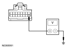
Is the voltage greater than 10 volts?
Yes
GO to K6.
No
VERIFY the Smart Junction Box (SJB) fuse 31 (10A) is OK. If OK, REPAIR the circuit. If not OK, REFER to the Wiring Diagrams to identify the possible causes of the circuit short Electrical Diagrams. TEST the system for normal operation.
K6 CHECK THE AUTO-DIMMING INTERIOR MIRROR REVERSE INPUT CIRCUIT
- Apply the parking brake.
- Select REVERSE.
- Measure the voltage between the auto-dimming interior mirror C9039-2, circuit CLS10 (GN/BN), harness side and ground.
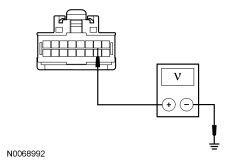
Is the voltage greater than 10 volts?
Yes
GO to K7.
No
REPAIR the circuit. TEST the system for normal operation.
K7 CHECK THE AUTO-DIMMING INTERIOR MIRROR GROUND CIRCUIT FOR AN OPEN
- Ignition OFF.
- Disconnect: Negative Battery Cable.
- Measure the resistance between the auto-dimming interior mirror C9039-3, circuit GD133 (BK), harness side and ground.
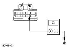
Is the resistance less than 5 ohms?
Yes
INSTALL a new auto-dimming interior mirror. TEST the system for normal operation.
No
REPAIR the circuit. TEST the system for normal operation.
K8 VERIFY THE ACM (Audio Control Module) DTCs
- Review the recorded DTCs from the ACM (Audio Control Module) self-test.
Is DTC C1001:01 or DTC U0155:00 present?
Yes
For DTC C1001:01, GO to K10.
For DTC U0155:00, REFER to Accessories and Optional Equipment. Collision Avoidance and Parking Assist Systems
No
GO to K9.
K9 CHECK THE ACM (Audio Control Module) DISPLAY
- Select REVERSE.
- Observe the ACM (Audio Control Module) display.
Does the ACM (Audio Control Module) display "PLEASE CHECK SURROUNDINGS FOR SAFETY" at the top of the display screen?
Yes
The ACM (Audio Control Module) is functional. There is no signal from the video camera. GO to K10.
No
INSTALL a new ACM (Audio Control Module). TEST the system for normal operation.
K10 CHECK THE VIDEO SIGNAL CIRCUITS INTEGRITY
- Ignition OFF.
- Disconnect: Auto-Dimming Interior Mirror (Without Navigation) C9039.
- Disconnect: ACM (Audio Control Module) (With Navigation) C240B.
- For vehicles without navigation, measure the resistance between the auto-dimming interior mirror C9039-8, circuit VMP19 (WH/GN), harness side and the auto-dimming interior mirror C9039-16, circuit RMP19 (BN/VT), harness side.

- For vehicles with navigation, measure the resistance between the ACM (Audio Control Module) C240B-1, circuit VMP19 (WH/GN), harness side and the ACM (Audio Control Module) C240B-6, circuit RMP19 (BN/VT), harness side.

Is the resistance between 74 and 106 ohms?
Yes
GO to K11.
No
GO to K13.
K11 CHECK THE VIDEO CAMERA VOLTAGE SUPPLY CIRCUIT FOR AN OPEN
- Disconnect: Video Camera C4357 (Navigator) or C4360 (Expedition).
- Ignition ON.
- For Navigator, measure the voltage between the video camera C4357-1, circuit CBP35 (GN/BN), harness side and ground.
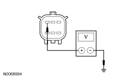
- For Expedition, measure the voltage between the video camera C4360-1, circuit CBP35 (TN), harness side and ground.
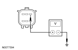
Is the voltage greater than 10 volts?
Yes
GO to K12.
No
REPAIR the circuit. TEST the system for normal operation.
K12 CHECK THE VIDEO CAMERA GROUND CIRCUIT FOR AN OPEN
- Ignition OFF.
- Disconnect: Negative Battery Cable.
- For Navigator, measure the resistance between the video camera C4357-6, circuit GD133 (BK), harness side and ground.

- For Expedition, measure the resistance between the video camera C4360-6, circuit GD133 (LG), harness side and ground.

Is the resistance less than 5 ohms?
Yes
GO to K18.
No
REPAIR the circuit. TEST the system for normal operation.
K13 CHECK THE VIDEO CAMERA VIDEO SIGNAL CIRCUITS FOR A SHORT TO GROUND
- Disconnect: Video Camera C4357 (Navigator) or C4360 (Expedition).
- For Navigator, measure the resistance between the video camera C4357-4, circuit VMP19 (WH/GN), harness side and ground; and between the video camera C4357-5, circuit RMP19 (BN/VT), harness side and ground.

- For Expedition, measure the resistance between the video camera C4360-4, circuit VMP19 (GY), harness side and ground; and between the video camera C4360-5, circuit RMP19 (BK), harness side and ground.

Are the resistances greater than 10,000 ohms?
Yes
GO to K14.
No
REPAIR the circuit. TEST the system for normal operation.
K14 CHECK THE VIDEO CAMERA VIDEO SIGNAL CIRCUITS FOR A SHORT TO SHIELD
- For Navigator, measure the resistance between the video camera C4357-4, circuit VMP19 (WH/GN), harness side and the video camera C4357-2, circuit DMP19 (BK), harness side.

- For Expedition, measure the resistance between the video camera C4360-4, circuit VMP19 (GY), harness side and the video camera C4360-2, circuit DMP19 (OG), harness side.

- Measure the resistance between the video camera C4357-5, circuit RMP19 (BN/VT) (Navigator) or C4360-5, circuit RMP19 (BK) (Expedition), harness side and the video camera C4357-2, circuit DMP19 (BK) (Navigator) or C4360-2, circuit DMP19 (OG) (Expedition), harness side.

Are the resistances greater than 10,000 ohms?
Yes
GO to K15.
No
REPAIR the circuit in question. TEST the system for normal operation.
K15 CHECK THE VIDEO CAMERA VIDEO SIGNAL CIRCUITS FOR A SHORT TO VOLTAGE
- Connect: Negative Battery Cable.
- Ignition ON.
- For Navigator, measure the voltage between the video camera C4357-4, circuit VMP19 (WH/GN), harness side and ground.
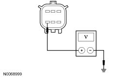
- For Expedition, measure the voltage between the video camera C4360-4, circuit VMP19 (GY), harness side and ground.
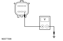
- Measure the voltage between the video camera C4357-5, circuit RMP19 (BN/VT) (Navigator) or C4360-5, circuit RMP19 (BK) (Expedition), harness side and ground.
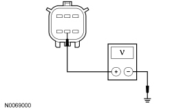
Is any voltage present?
Yes
REPAIR the circuit in question. TEST the system for normal operation.
No
GO to K16.
K16 CHECK VIDEO SIGNAL CIRCUITS FOR AN OPEN
- Ignition OFF.
- For Navigator, connect a fused jumper wire between the video camera C4357-4, circuit VMP19 (WH/GN), harness side and the video camera C4357-5, circuit RMP19 (BN/VT), harness side.

- For Expedition, connect a fused jumper wire between the video camera C4360-4, circuit VMP19 (GY), harness side and the video camera C4360-5, circuit RMP19 (BK), harness side.

- For vehicles without navigation, measure the resistance between the auto-dimming interior mirror C9039-8, circuit VMP19 (WH/GN), harness side and the auto-dimming interior mirror C9039-16, circuit RMP19 (BN/VT), harness side.
- For vehicles with navigation, measure the resistance between the ACM (Audio Control Module) C240B-1, circuit VMP19 (WH/GN), harness side and the ACM (Audio Control Module) C240B-6, circuit RMP19 (BN/VT), harness side.
Are the resistances less than 5 ohms?
Yes
REMOVE the jumper wire. GO to K18.
No
REMOVE the jumper wire. GO to K17.
K17 CHECK THE VIDEO (+) SIGNAL CIRCUIT FOR AN OPEN
- For Navigator without navigation, measure the resistance between the auto-dimming interior mirror C9039-8, circuit VMP19 (WH/GN), harness side and the video camera C4357-4, circuit VMP19 (WH/GN), harness side.

- For Expedition without navigation, measure the resistance between the auto-dimming interior mirror C9039-8, circuit VMP19 (WH/GN), harness side and the video camera C4360-4, circuit VMP19 (GY), harness side.

- For Navigator with navigation, measure the resistance between the ACM (Audio Control Module) C240B-1, circuit VMP19 (WH/GN), harness side and the video camera C4357-4, circuit VMP19 (WH/GN), harness side.

- For Expedition with navigation, measure the resistance between the ACM (Audio Control Module) C240B-1, circuit VMP19 (WH/GN), harness side and the video camera C4360-4, circuit VMP19 (GY), harness side.

Are the resistances less than 5 ohms?
Yes
REPAIR circuit RMP19 (BN/VT). TEST the system for normal operation.
No
REPAIR circuit VMP19 (WH/GN). TEST the system for normal operation.
K18 CHECK FOR CORRECT VIDEO CAMERA OPERATION
- Connect all disconnected connectors.
- Disconnect the video camera connector.
- Check for:
- corrosion
- damaged pins
- pushed-out pins
- Connect the video camera connector and make sure it seats correctly.
- Operate the system and verify the concern is still present.
Is the concern still present?
Yes
INSTALL a new video camera. REFER to Video Camera . TEST the system for normal operation.
No
The system is operating correctly at this time. The concern may have been caused by a loose or corroded connector.