Part 2
Camshaft
WARNING: Do not smoke, carry lighted tobacco or have an open flame of any type when working on or near any fuel-related component. Highly flammable mixtures are always present and may be ignited. Failure to follow these instructions may result in serious personal injury.
NOTICE: During engine repair procedures, cleanliness is extremely important. Any foreign material, including any material created while cleaning gasket surfaces that enters the oil passages, coolant passages or the oil pan, may cause engine failure.
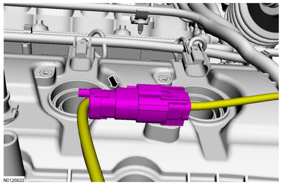
71. Disconnect the LH Heated Oxygen Sensor (HO2S) electrical connector.
- Detach the wiring harness connector pin-type retainer from the LH valve cover.
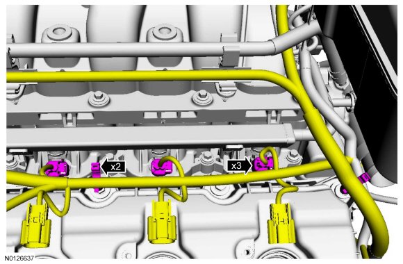
72. Disconnect the 3 fuel injector electrical connectors.
- Detach the 2 wiring harness retainers from the LH valve cover stud bolts.
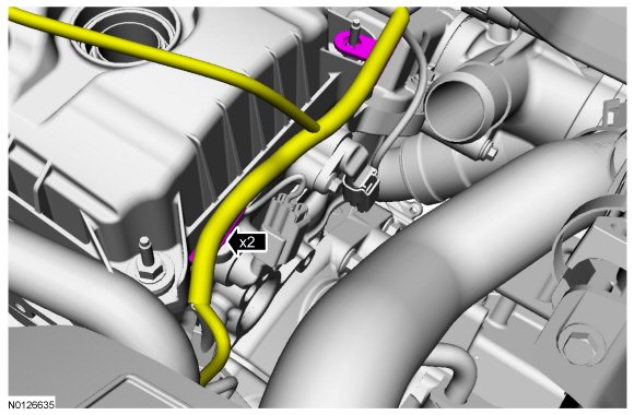
73. Detach the 2 wiring harness retainers and position the harness aside.
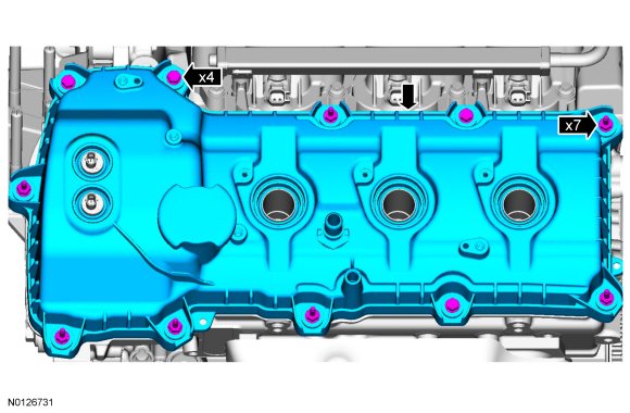
74. NOTICE: While removing the valve cover do not apply excessive force to the Variable Camshaft Timing (VCT) oil control solenoid or damage may occur.
NOTICE: If the Variable Camshaft Timing (VCT) oil control solenoid sticks to the VCT (Variable Camshaft Timing) seal, carefully wiggle the valve cover until the bond breaks free or damage to the VCT (Variable Camshaft Timing) seal and VCT (Variable Camshaft Timing) oil control solenoid may occur.
Loosen the 4 bolts and 7 stud bolts.
- Remove the LH valve cover.
- Discard the gasket.
75. Disconnect the Evaporative Emission (EVAP) canister vent solenoid and throttle body electrical connectors.
- Detach the wiring harness pin-type retainer.
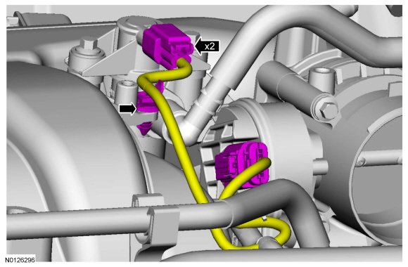
76. Disconnect the EVAP (Evaporative Emission) vapor tube from the EVAP (Evaporative Emission) canister vent solenoid.
- Detach the EVAP (Evaporative Emission) tube retainer.
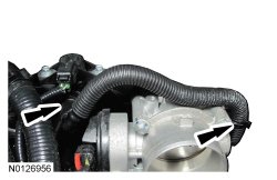
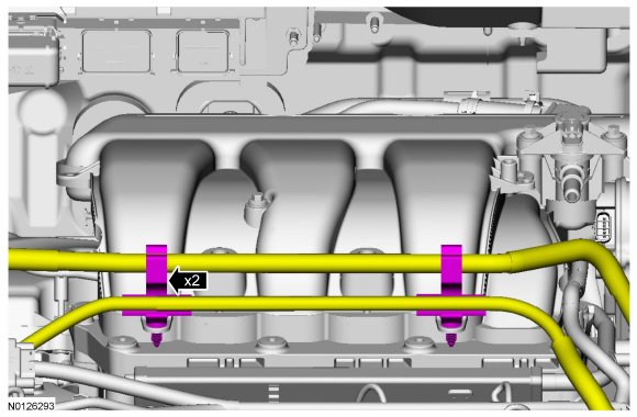
77. Detach the 2 wiring harness/coolant tube retainers from the upper intake manifold.
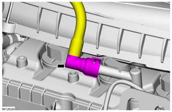
78. Disconnect the crankcase ventilation hose from the Positive Crankcase Ventilation (PCV) valve.
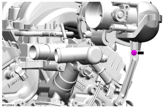
79. Remove the upper intake manifold support bracket bolt.
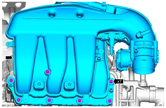
80. Remove the 7 bolts and the upper intake manifold.
- Remove and discard the gasket.
- Clean and inspect all of the sealing surfaces of the upper and lower intake manifold.
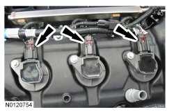
81. Disconnect the 3 RH coil-on-plug electrical connectors.
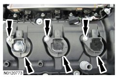
82. Remove the 3 bolts and the 3 RH -coil-on-plugs.
83. Disconnect the HO2S (Heated Oxygen Sensor) and CMS (Catalyst Monitor Sensor) electrical connectors.
- Detach the 2 wiring harness retainers from the RH valve cover.
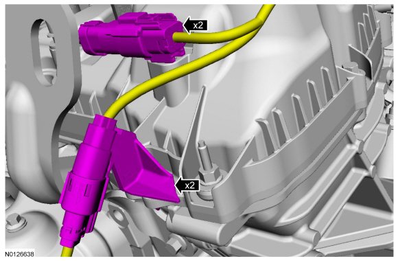
84. Disconnect the 2 Variable Camshaft Timing (VCT) oil control solenoid electrical connectors.
- Detach the 2 wiring harness retainers.
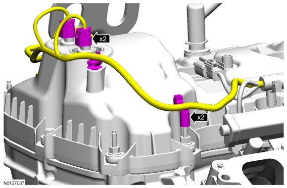
85. Disconnect the 3 fuel injector electrical connectors.
- Detach the 2 wiring harness retainers.
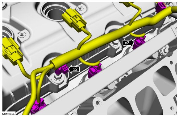
86. Detach the wiring harness retainer.
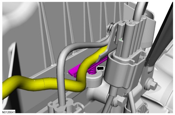
87. Remove the 2 nuts and position aside the 2 power steering hose brackets.
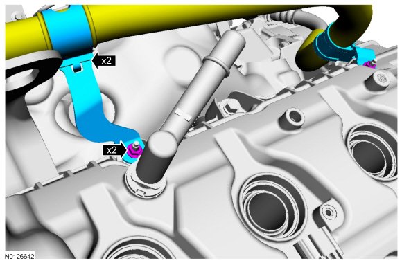
88. NOTICE: While removing the valve cover do not apply excessive force to the Variable Camshaft Timing (VCT) oil control solenoid or damage may occur.
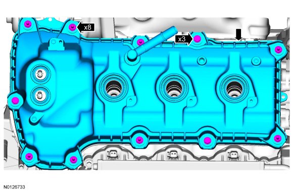
NOTICE: If the Variable Camshaft Timing (VCT) oil control solenoid sticks to the VCT (Variable Camshaft Timing) seal, carefully wiggle the valve cover until the bond breaks free or damage to the VCT (Variable Camshaft Timing) seal and VCT (Variable Camshaft Timing) oil control solenoid may occur.
Loosen the 3 bolts and 8 stud bolts.
- Remove the RH valve cover.
- Discard the gasket.
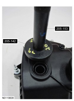
89. NOTE: LH shown, RH similar.
Inspect the VCT (Variable Camshaft Timing) solenoid seals. Remove any damaged seals.
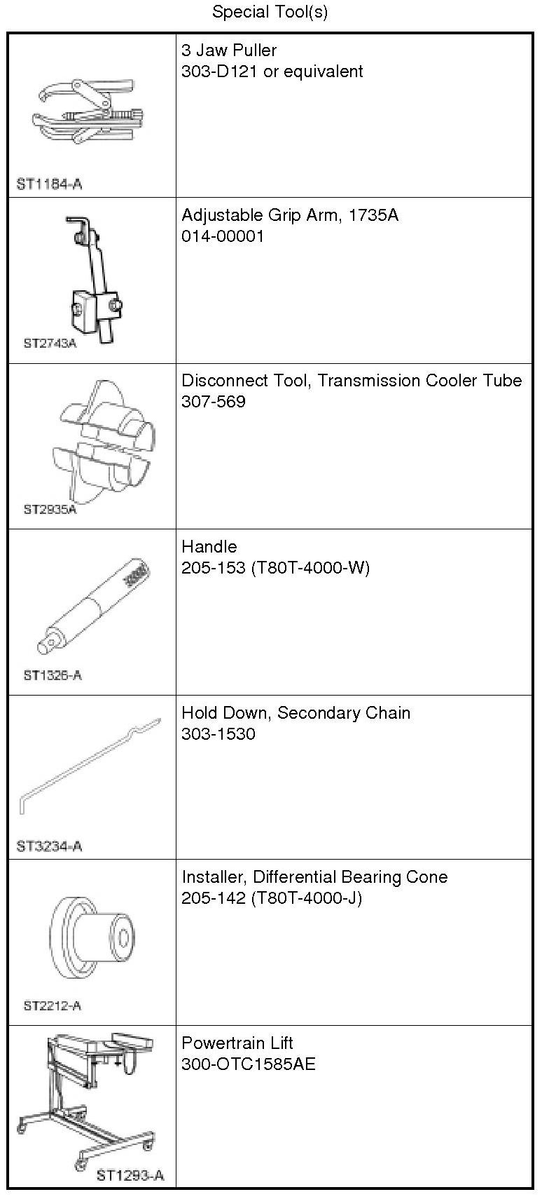
- Using the Differential Bearing Cone Installer and Handle, remove and discard the seal(s).
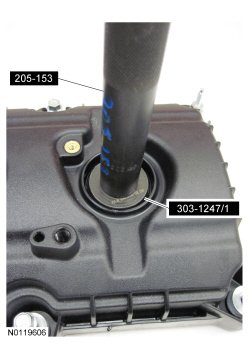
90. NOTE: LH shown, RH similar.
Inspect the spark plug tube seals. Remove any damaged seals.
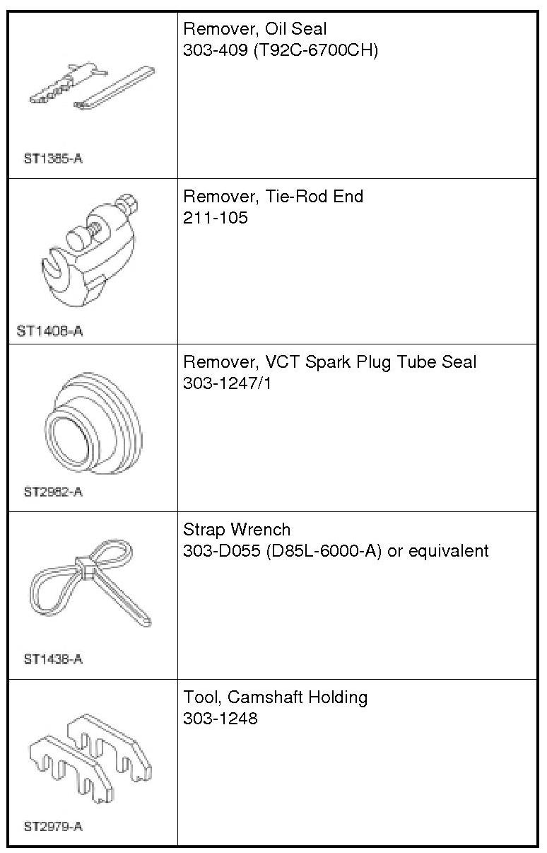
- Using the Spark Plug Tube Seal Remover and Handle, remove and discard the seal(s).
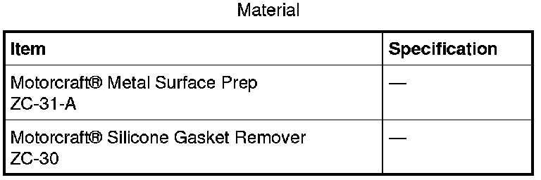
91. Clean the valve covers, cylinder heads and engine front cover sealing surfaces with metal surface prep.
92. NOTE: Power steering hoses removed from graphic for clarity.
Remove the 3 bolts and the power steering pump.
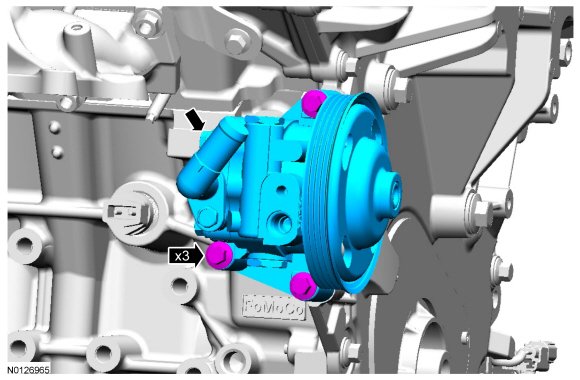
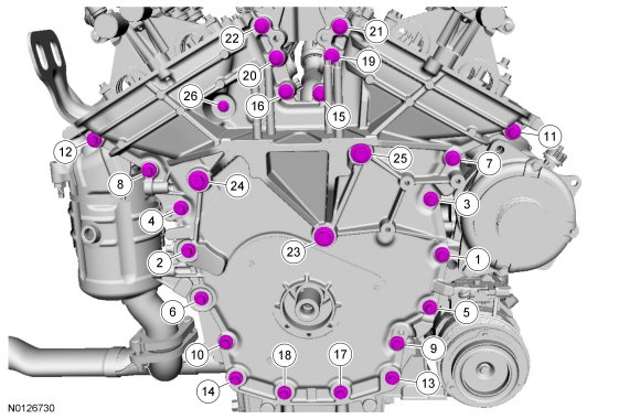
93. Remove the 26 front cover bolts.
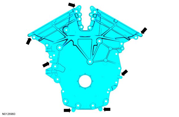
94. Using a suitable pry tool, locate the 7 pry pads shown and pry the engine front cover loose and remove.
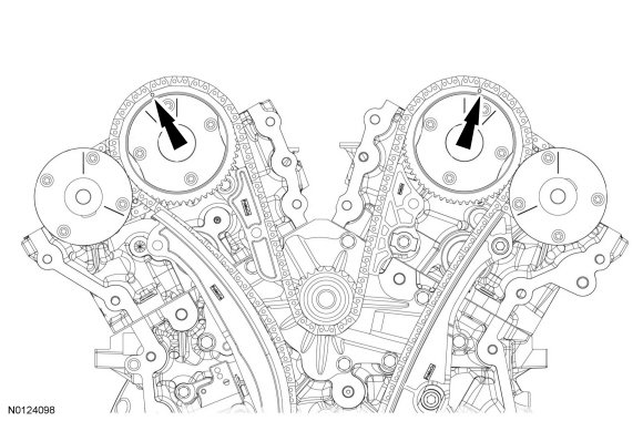
95. Rotate the crankshaft clockwise and align the timing marks on the intake Variable Camshaft Timing (VCT) assemblies as shown.
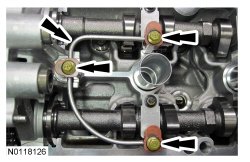
96. Remove the 3 bolts and the LH valve train oil tube.
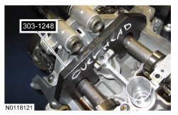
97. NOTE: The Camshaft Holding Tool will hold the camshafts in the Top Dead Center (TDC) position.
Install the Camshaft Holding Tool onto the flats of the LH camshafts.
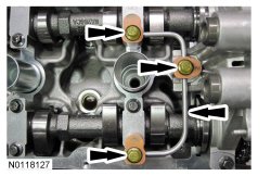
98. Remove the 3 bolts and the RH valve train oil tube.
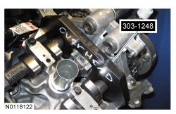
99. NOTE: The Camshaft Holding Tool will hold the camshafts in the TDC (Top Dead Center) position.
Install the Camshaft Holding Tool onto the flats of the RH camshafts.
NOTE: The following 3 steps are for primary timing chains that the colored links are not visible.
100. Mark the timing chain link that aligns with the timing mark on the LH intake VCT (Variable Camshaft Timing) assembly as shown.
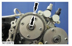
101. Mark the timing chain link that aligns with the timing mark on the RH intake VCT (Variable Camshaft Timing) assembly as shown.

102. NOTE: The crankshaft sprocket timing mark should be between the 2 colored links.
Mark the 2 timing chain links that align with the timing mark on the crankshaft sprocket as shown.
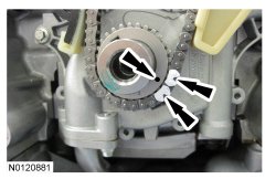
103. Remove the 2 bolts and the primary timing chain tensioner.
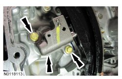
104. Remove the primary timing chain tensioner arm.
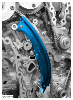
105. Remove the 2 bolts and the lower LH primary timing chain guide.
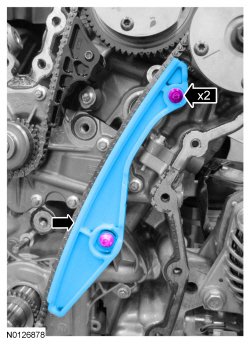
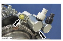
106. NOTE: Removal of the VCT (Variable Camshaft Timing) oil control solenoid will aid in the removal of the primary timing chain.
NOTE: A slight twisting motion will aid in the removal of the VCT (Variable Camshaft Timing) oil control solenoid.
NOTE: Keep the VCT (Variable Camshaft Timing) oil control solenoid clean of dirt and debris.
Remove the bolt and the LH intake VCT (Variable Camshaft Timing) oil control solenoid.
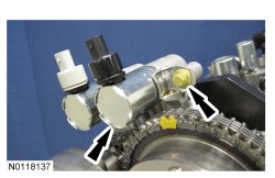
107. NOTE: Removal of the VCT (Variable Camshaft Timing) oil control solenoid will aid in the removal of the primary timing chain.
NOTE: A slight twisting motion will aid in the removal of the VCT (Variable Camshaft Timing) oil control solenoid.
NOTE: Keep the VCT (Variable Camshaft Timing) oil control solenoid clean of dirt and debris.
Remove the bolt and the RH intake VCT (Variable Camshaft Timing) oil control solenoid.
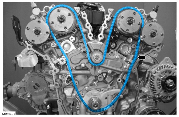
108. Remove the primary timing chain.
LH camshafts
109. NOTE: The 2 VCT (Variable Camshaft Timing) oil control solenoids are removed for clarity.
NOTE: The Secondary Chain Hold Down is inserted through a hole in the top of the mega cap.
Compress the LH secondary timing chain tensioner and install the Secondary Chain Hold Down in the hole on the rear of the secondary timing chain tensioner guide and let it hold against the mega cap to retain the tensioner in the collapsed position.
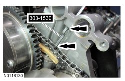
110. Remove and discard the 2 LH VCT (Variable Camshaft Timing) assembly bolts.
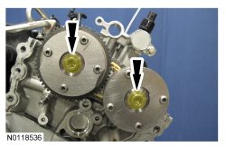
111. Remove the 2 LH VCT (Variable Camshaft Timing) assemblies and secondary timing chain.
- Remove the Secondary Chain Hold Down.
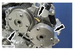
112. NOTE: When the Camshaft Holding Tool is removed, valve spring pressure may rotate the LH camshafts approximately 3 degrees to a neutral position.
Remove the Camshaft Holding Tool from the LH camshafts.
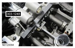
113. NOTE: Cylinder head camshaft bearing caps are numbered to verify that they are assembled in their original positions.
NOTE: Mark the exhaust and intake camshafts for installation into their original locations.
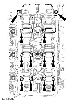
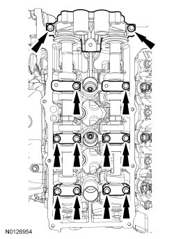
Remove the 12 bolts, 6 camshaft caps, mega cap and the LH camshafts.
RH camshafts
114. NOTE: The 2 VCT (Variable Camshaft Timing) oil control solenoids are removed for clarity.
NOTE: The Secondary Chain Hold Down is inserted through a hole in the top of the mega cap.
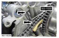
Compress the RH secondary timing chain tensioner and install the Secondary Chain Hold Down in the hole on the rear of the secondary timing chain tensioner guide and let it hold against the mega cap to retain the tensioner in the collapsed position.
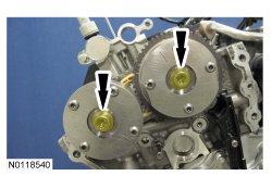
115. Remove and discard the 2 RH VCT (Variable Camshaft Timing) assembly bolts.
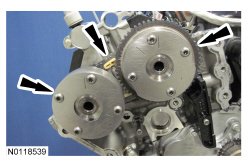
116. Remove the 2 RH VCT (Variable Camshaft Timing) assemblies and secondary timing chain.
- Remove the Secondary Chain Hold Down.
117. NOTE: When the Camshaft Holding Tool is removed, valve spring pressure may rotate the RH camshafts approximately 3 degrees to a neutral position.
Remove the Camshaft Holding Tool from the RH camshafts.
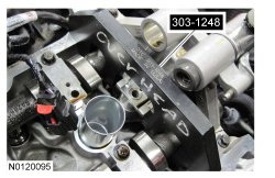
118. NOTE: Cylinder head camshaft bearing caps are numbered to verify that they are assembled in their original positions.
NOTE: Mark the exhaust and intake camshafts for installation into their original locations.
Remove the 12 bolts, 6 camshaft caps, mega cap and the RH camshafts.