Steering Column
Steering Column
Removal and Installation
NOTE: Non-commercial chassis shown, commercial chassis similar.
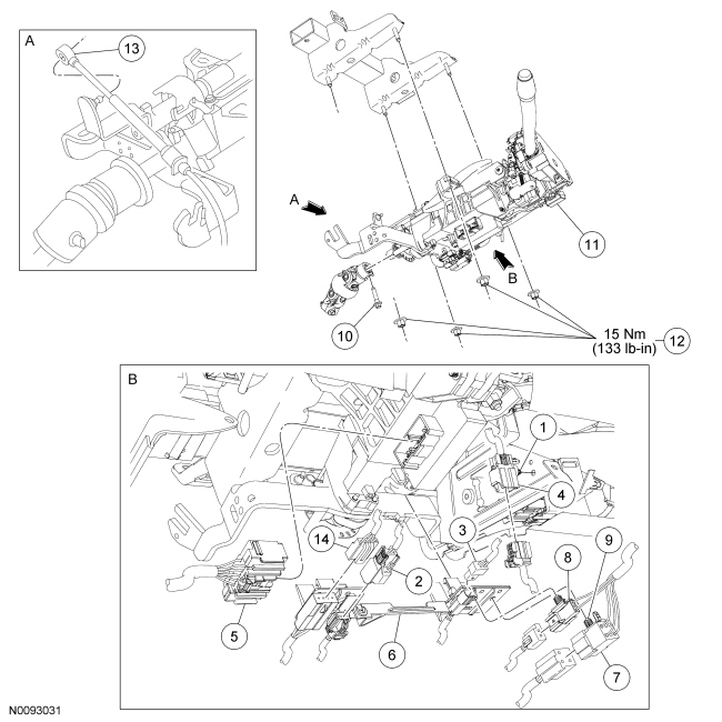
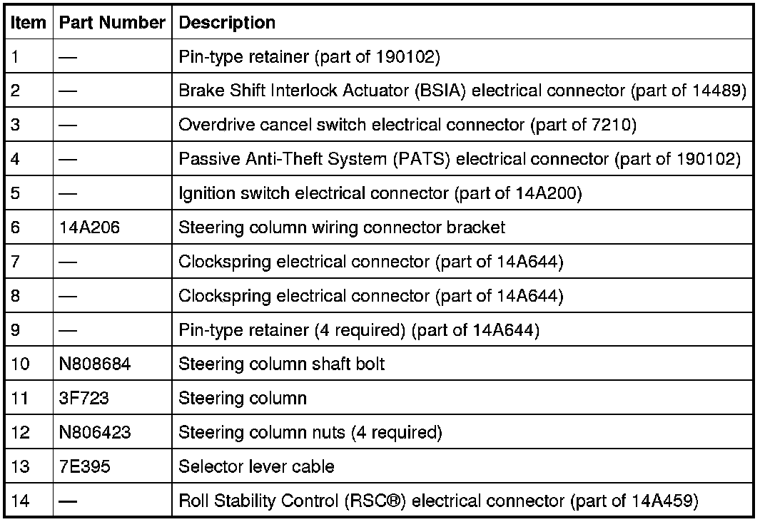
NOTE: All steering column components are assembled with specific fasteners. They are designed with a thread-locking system to prevent loosening due to vibrations associated with normal vehicle operation.
All vehicles
1. Remove the steering wheel. For additional information, refer to Steering Wheel Steering Wheel.
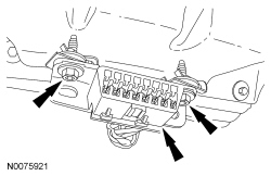
2. Remove the 2 Data Link Connector (DLC) screws and position the DLC (Data Link Connector) aside.
3. Remove the steering column opening cover and the instrument panel LH knee bolster.
4. Remove the multifunction switch.
5. Reinstall the ignition lock cylinder and remove the key.
Commercial chassis
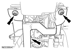
6. Remove the 2 lower steering column support bracket nuts.
- To install, tighten to 18 Nm (159 lb-in).
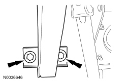
7. Remove the 2 upper steering column support bracket nuts and the steering column support bracket.
- To install, tighten to 18 Nm (159 lb-in).
All vehicles
8. Disconnect the Brake Shift Interlock Actuator (BSIA) electrical connector and detach the pin-type retainer from the bend bracket.
Commercial chassis
9. NOTICE: Do not allow the steering column to rotate while the steering column shaft is disconnected or damage to the clockspring may result. If there is evidence that the steering column has rotated, the clockspring must be removed and recentered. For additional information, refer to Restraints and Safety Systems &/or Air Bag Systems.
Remove the bolt and detach the upper steering column shaft from the steering column.
- To install, tighten to 40 Nm (30 lb-ft).
All except commercial chassis
10. NOTICE: Do not allow the steering column to rotate while the steering column shaft is disconnected or damage to the clockspring can result. If there is evidence that the steering column has rotated, the clockspring must be removed and recentered. For additional information, refer to Restraints and Safety Systems &/or Air Bag Systems.
Remove the bolt and detach the steering column coupling and shaft from the steering column.
- To install, tighten to 25 Nm (18 lb-ft).
All vehicles
11. Disconnect the selector lever cable from the selector lever pivot arm.
12. Remove the selector lever cable from the steering column by pushing the tab on the cable in and sliding the cable off the mounting bracket.
13. Disconnect the Passive Anti-Theft System (PATS) electrical connector.
- Detach the PATS (Passive Anti-Theft System) electrical connector pin-type retainer from the instrument panel support bracket.
14. Disconnect the ignition switch electrical connector.
15. Disconnect the overdrive cancel switch electrical connector and the 2 clockspring electrical connectors at the base of the steering column.
16. Detach the 2 clockspring electrical connector pin-type retainers from the steering column bend bracket.
17. If equipped, disconnect the Roll Stability Control (RSC(R)) electrical connector and detach the pin-type retainer from the bend bracket.
18. Detach the steering column bend bracket from the steering column and position it aside.
19. While supporting the steering column, remove the 4 nuts and the steering column.
- To install, tighten to 15 Nm (133 lb-in).
20. To install, reverse the removal procedure.