Pinpoint Test J: The Vehicle Does Not Start With The IA Key In Certain Areas Within The Vehicle
- J1 CHECK THE IA KEY LOCATION
- Check the location of the IA key and if it is placed in the overhead console, far corners of the rear seat, far outside edges of the windshield, or above the sun visors, move the IA key out of these areas and attempt to start the vehicle.
- Does the vehicle start?
- Yes
: The system is OK. INFORM the customer of the normal vehicle operation.
- No
: GO to J2.
- J2 CHECK THE SUSPECT PASSIVE START ANTENNA
- Ignition OFF.
- Disconnect: Suspect Passive Start Antenna.
- Measure the resistance between the suspect passive start antenna pin 1, component side and the suspect passive start antenna pin 2, component side.
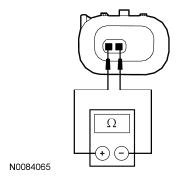 Courtesy of FORD MOTOR CO.
- Is the resistance between 1 and 10 ohms?
- J3 CHECK THE PASSIVE START ANTENNA CIRCUITS FOR A SHORT TO VOLTAGE
- Disconnect: RFA Module C2153A.
- Ignition ON.
- Measure the voltage between the suspect passive start antenna, harness side and ground as follows:
| Suspect Passive Start Antenna Connector-Pin |
Circuit |
| Front C325-1 |
VPK05 (BN/GN) |
| Front C325-2 |
RPK05 (YE/OG) |
| Center C326-1 |
VPK06 (GY/VT) |
| Center C326-2 |
RPK06 (BU/WH) |
| Rear C317-1 |
VPK08 (WH/OG) |
| Rear C317-2 |
RPK08 (BN/VT) |
 Courtesy of FORD MOTOR CO.
- Is any voltage present?
- Yes
: GO to J4.
- No
: REPAIR the circuit in question for a short to voltage. TEST the system for normal operation.
- J4 CHECK THE PASSIVE START ANTENNA CIRCUITS FOR A SHORT TO GROUND
- Disconnect: RFA Module C2153a.
- Measure the resistance between the suspect passive start antenna, harness side and ground as follows:
| Suspect Passive Start Antenna Connector-Pin |
Circuit |
| Front C325-1 |
VPK05 (BN/GN) |
| Front C325-2 |
RPK05 (YE/OG) |
| Center C326-1 |
VPK06 (GY/VT) |
| Center C326-2 |
RPK06 (BU/WH) |
| Rear C317-1 |
VPK08 (WH/OG) |
| Rear C317-2 |
RPK08 (BN/VT) |
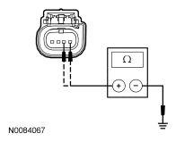 Courtesy of FORD MOTOR CO.
- Is the resistance greater than 10, 000 ohms?
- Yes
: GO to J5.
- No
: REPAIR the circuit in question for a short to ground. TEST the system for normal operation.
- J5 CHECK THE CIRCUITS FOR AN OPEN
- Measure the resistance between the RFA module C2153a, harness side and the suspect passive start antenna connector, harness side as follows:
| RFA Module Connector-Pin |
Suspect Passive Start Antenna Connector-Pin |
Circuit |
| C2153a-1 |
Front C325-1 |
VPK05 (BN/GN) |
| C2153a-2 |
Front C325-2 |
RPK05 (YE/OG) |
| C2153a-3 |
Center C326-1 |
VPK06 (GY/VT) |
| C2153a-4 |
Center C326-2 |
RPK06 (BU/WH) |
| C2153a-5 |
Rear C317-1 |
VPK08 (WH/OG) |
| C2153a-14 |
Rear C317-2 |
RPK08 (BN/VT) |
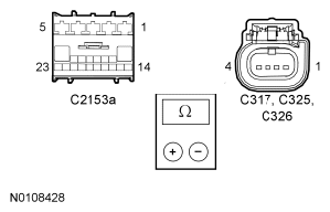 Courtesy of FORD MOTOR CO.
- Are the resistances less than 5 ohms?
- Yes
: GO to J6.
- No
: REPAIR the circuit in question for an open. CLEAR the DTCs. REPEAT the self-test.
- J6 CHECK FOR CORRECT RFA MODULE OPERATION
- Disconnect all the RFA module connectors.
- Check for:
- corrosion
- damaged pins
- pushed-out pins
- Connect all the RFA module connectors and make sure they seat correctly.
- Operate the system and verify the concern is still present.
- Is the concern still present?
- Yes
: INSTALL a new RFA module. REFER to
MULTIFUNCTION ELECTRONIC MODULE
Article. TEST the system for normal operation
- No
: The system is operating correctly at this time. The concern may have been caused by a loose or corroded connector.