Pinpoint Test L: One Or More Parking, Rear Or License Plate Lamps Is Inoperative
Parking, Rear and License Plate Lamps
Pinpoint Tests
Pinpoint Test L: One Or More Parking, Rear Or License Plate Lamps Is Inoperative
Refer to Wiring Diagram Set 92, Parking, Rear and License Lamps for schematic and connector information. Diagrams By Number
Normal Operation
The parking lamp relay is integrated into, and controlled by, the Smart Junction Box (SJB). The headlamp switch is provided voltage at all times. When the headlamp switch is placed in the PARKING LAMPS ON position, the headlamp switch routes the voltage to the SJB. When the SJB receives the voltage signal from the headlamp switch, the parking lamp relay (integrated into the SJB) is energized and voltage is routed to the parking lamps.
This pinpoint test is intended to diagnose the following:
- Fuse
- Wiring, terminals or connectors
- Headlamp switch
- SJB
PINPOINT TEST L: ONE OR MORE PARKING, REAR OR LICENSE PLATE LAMPS IS INOPERATIVE
NOTICE: Use the correct probe adapter(s) when making measurements. Failure to use the correct probe adapter(s) may damage the connector.
NOTE: Failure to disconnect the battery when instructed will result in false resistance readings. Refer to Battery, Mounting and Cables Battery Disconnect.
-------------------------------------------------
L1 DETERMINE IF ALL THE PARKING LAMPS ARE INOPERATIVE
- Ignition OFF.
- Place the headlamp switch in the PARKING LAMPS ON position.
- Are all the parking lamps inoperative?
Yes
VERIFY the SJB fuse 31 (20A) is OK. If OK, GO to L2. If not OK, REFER to the Wiring Diagrams to identify the possible causes of the circuit short. Diagrams By Number
No
If all the front or all the rear parking lamps are inoperative, GO to L6.
If an individual parking lamp is inoperative, GO to L8.
-------------------------------------------------
L2 CHECK THE HEADLAMP OPERATION
- Place the headlamp switch in the HEADLAMPS ON position.
- Do the headlamps operate correctly?
Yes
GO to L3.
No
REFER to Headlamps Special Tool(s) Used With Diagnostics.
-------------------------------------------------
L3 CHECK THE HEADLAMP SWITCH
- Place the headlamp switch in the OFF position.
- Disconnect: Headlamp Switch C205.
- Carry out the headlamp switch component test.
Refer to Headlamp Switch for component testing. Diagrams By Number
- Is the headlamp switch OK?
Yes
GO to L4.
No
INSTALL a new headlamp switch. REFER to Headlamp Switch Service and Repair. TEST the system for normal operation.
-------------------------------------------------
L4 CHECK FOR VOLTAGE TO THE HEADLAMP SWITCH
- Measure the voltage between the headlamp switch C205-10, circuit SBP23 (WH/RD), harness side and ground.
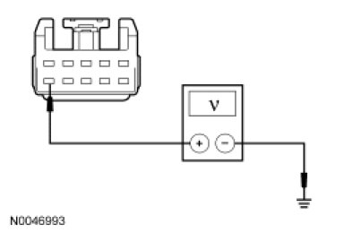
- Is the voltage greater than 10 volts?
Yes
GO to L5.
No
REPAIR circuit SBP23 (WH/RD) for an open. TEST the system for normal operation.
-------------------------------------------------
L5 CHECK THE HEADLAMP SWITCH OUTPUT CIRCUIT FOR AN OPEN
- Disconnect: SJB C2280d.
- Measure the resistance between the headlamp switch C205-5, circuit CLS30 (VT/WH), harness side and the SJB C2280d-5, circuit CLS30 (VT/WH), harness side.
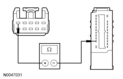
- Is the resistance less than 5 ohms?
Yes
GO to L9.
No
REPAIR circuit CLS30 (VT/WH) for an open. TEST the system for normal operation.
-------------------------------------------------
L6 CHECK THE SJB PARKING LAMP OUTPUT CIRCUIT FOR AN OPEN
- Place the headlamp switch in the OFF position.
- Disconnect: SJB C2280a (Front Parking Lamps).
- Disconnect: SJB C2280c (Rear Parking Lamps).
- Measure the resistance between the SJB C2280c-3 (rear parking lamps), circuit CLS34 (GY), harness side and ground; or between the SJB C2280a-12 (front parking lamps), circuit CLS34 (GY), harness side and ground.
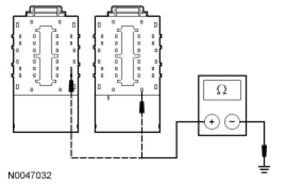
- Is the resistance less than 5 ohms?
Yes
GO to L9.
No
For the front parking lamps, REPAIR circuit CLS34 (GY) for an open. TEST the system for normal operation.
For the rear parking lamps, GO to L7.
-------------------------------------------------
L7 CHECK THE REAR LAMPS GROUND CIRCUIT FOR AN OPEN
- Disconnect: Negative Battery Cable.
- Disconnect: LH Rear Lamp C412.
- Measure the resistance between the LH rear lamp C412-1, circuit GD121 (BK/YE), harness side and ground.
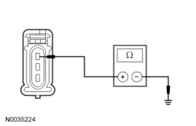
- Is the resistance less than 5 ohms?
Yes
REPAIR circuit CLS34 (GY) for an open. TEST the system for normal operation.
No
REPAIR circuit GD121 (BK/YE) for an open. TEST the system for normal operation.
-------------------------------------------------
L8 CHECK FOR VOLTAGE TO THE INOPERATIVE LAMP
- Place the headlamp switch in the OFF position.
- Disconnect: Inoperative Parking Lamp.
- Place the headlamp switch in the ON position.
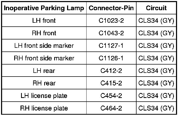
- Measure the voltage between the inoperative lamp, harness side and ground as follows.
- Is the voltage greater than 10 volts?
Yes
REPAIR the ground circuit in question for an open. TEST the system for normal operation.
No
REPAIR circuit CLS34 (GY) for an open. TEST the system for normal operation.
-------------------------------------------------
L9 CHECK FOR CORRECT SJB OPERATION
- Disconnect all the SJB connectors.
- Check for:
- corrosion
- damaged pins
- pushed-out pins
- Connect all the SJB connectors and make sure they seat correctly.
- Operate the system and verify the concern is still present.
- Is the concern still present?
Yes
INSTALL a new SJB. REFER to Multifunction Electronic Modules Service and Repair. TEST the system for normal operation.
No
The system is operating correctly at this time. The concern may have been caused by a loose or corroded connector.
-------------------------------------------------