Crankshaft Rear Seal With Retainer Plate
Crankshaft Rear Seal with Retainer Plate

Removal
NOTICE: During engine repair procedures, cleanliness is extremely important. Any foreign material, including any material created while cleaning gasket surfaces that enters the oil passages, coolant passages or the oil pan, can cause engine failure.
NOTE: Automatic transmission shown, manual transmission similar.
1. With the vehicle in NEUTRAL, position it on a hoist. For additional information, refer to Jacking and Lifting Service and Repair.
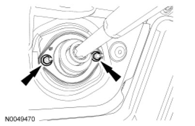
2. Remove the 2 steering column dash boot bearing nuts.
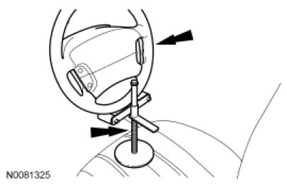
3. NOTE: Use a steering wheel holding device (such as Hunter(R) 28-75-1 or equivalent).
Using a suitable holding device, hold the steering wheel in the straight-ahead position.
4. Remove the Crankshaft Position (CKP) sensor. For additional information, refer to Electronic Engine Controls Exploded Views.
5. Remove the flexplate or flywheel. For additional information, refer to Flexplate Removal and Replacement or Flywheel Flywheel.
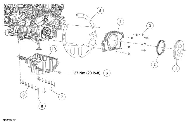
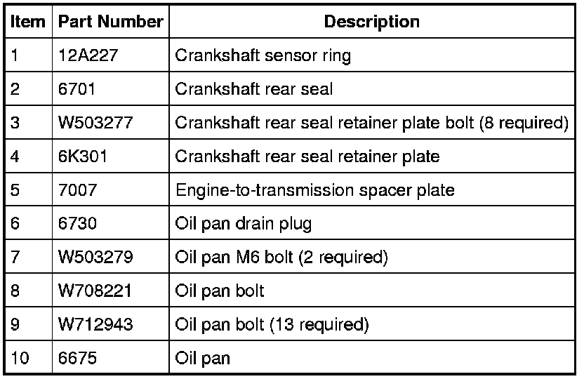
6. Remove the crankshaft sensor ring.
7. Remove the engine-to-transmission spacer plate.
8. Remove the oil level indicator.
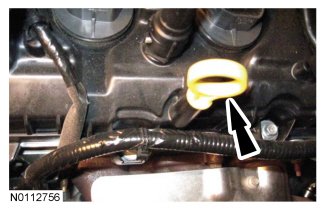
9. NOTE: RH shown, LH similar.
Remove the RH and LH engine mount-to-engine bracket mount nuts.
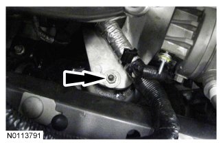
10. Remove the nut from the rear LH valve cover stud bolt and position the generator wiring harness bracket aside.
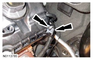
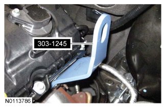
11. Install the LH engine lift eye.
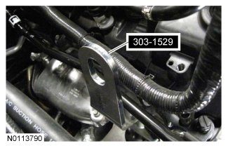
12. Install the RH front engine lift eye.
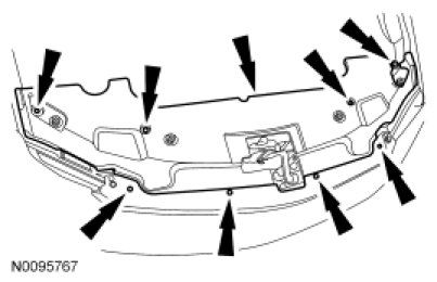
13. Remove the 8 pin-type retainers and the radiator sight shield.
14. Remove the 2 bolts and the RH radiator support bracket.
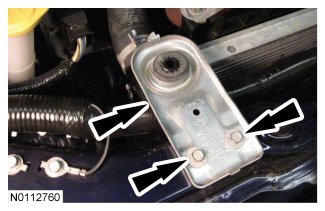
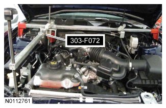
15. NOTICE: Do not position the legs of the Engine Support Bar on the fenders. Instead, position the legs on the body structure near the suspension strut tower. Failure to follow these instructions may result in body damage.
Install the Engine Support Bar.
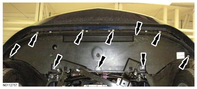
16. Remove the 9 bolts and the lower air deflector.
17. NOTE: RH shown, LH similar.
Loosen the 2 nuts for the crossmember brace.
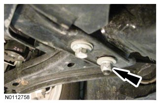
18. NOTE: RH shown, LH similar.
Remove the 6 bolts (2 shown) and slide the crossmember brace forward and remove.
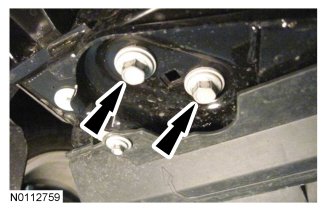
19. Remove the drain plug and drain the engine oil.
- Install the drain plug and tighten to 27 Nm (20 lb-ft).
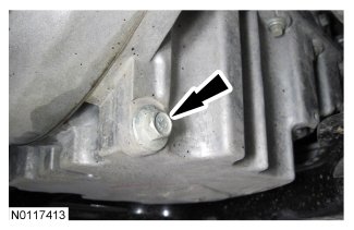
20. Disconnect the 2 Electronic Power Assist Steering (EPAS) electrical connectors.
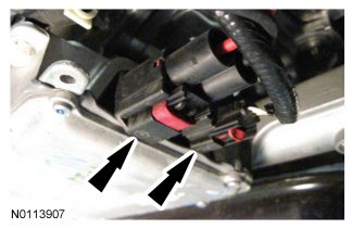
21. Detach the 2 EPAS wiring harness pin-type retainers.
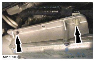
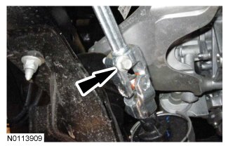
22. Remove the steering shaft pinch bolt and disconnect the steering shaft.
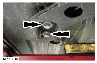
23. NOTE: Mark the position of the 4 subframe nuts and 4 subframe bolts for reference during installation.
NOTE: RH shown, LH similar.
Remove the 4 rear subframe bolts.
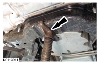
24. Using an adjustable jackstand, support the subframe.
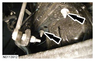
25. NOTE: RH shown, LH similar.
Remove the 4 front subframe nuts and lower the subframe, using the adjustable jackstand.
26. Remove the 4 lower engine front cover bolts.
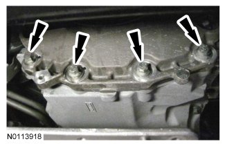
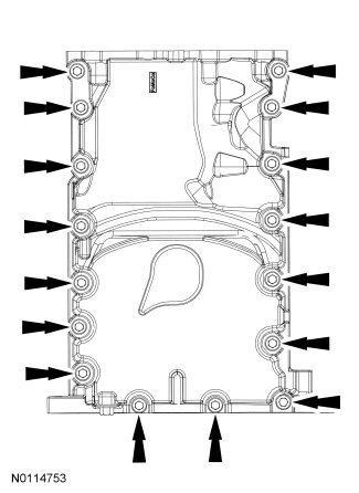
27. Remove the 16 oil pan bolts.
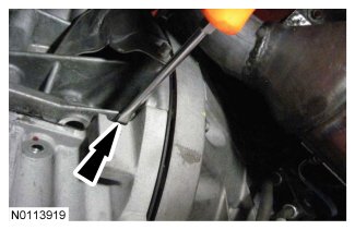
28. NOTE: LH rear shown, RH front similar.
NOTE: The subframe may need to be lowered more for clearance to remove the oil pan.
Using a suitable pry tool, locate the 2 pry pads at the LH rear and RH front of oil pan and pry the oil pan loose and remove.
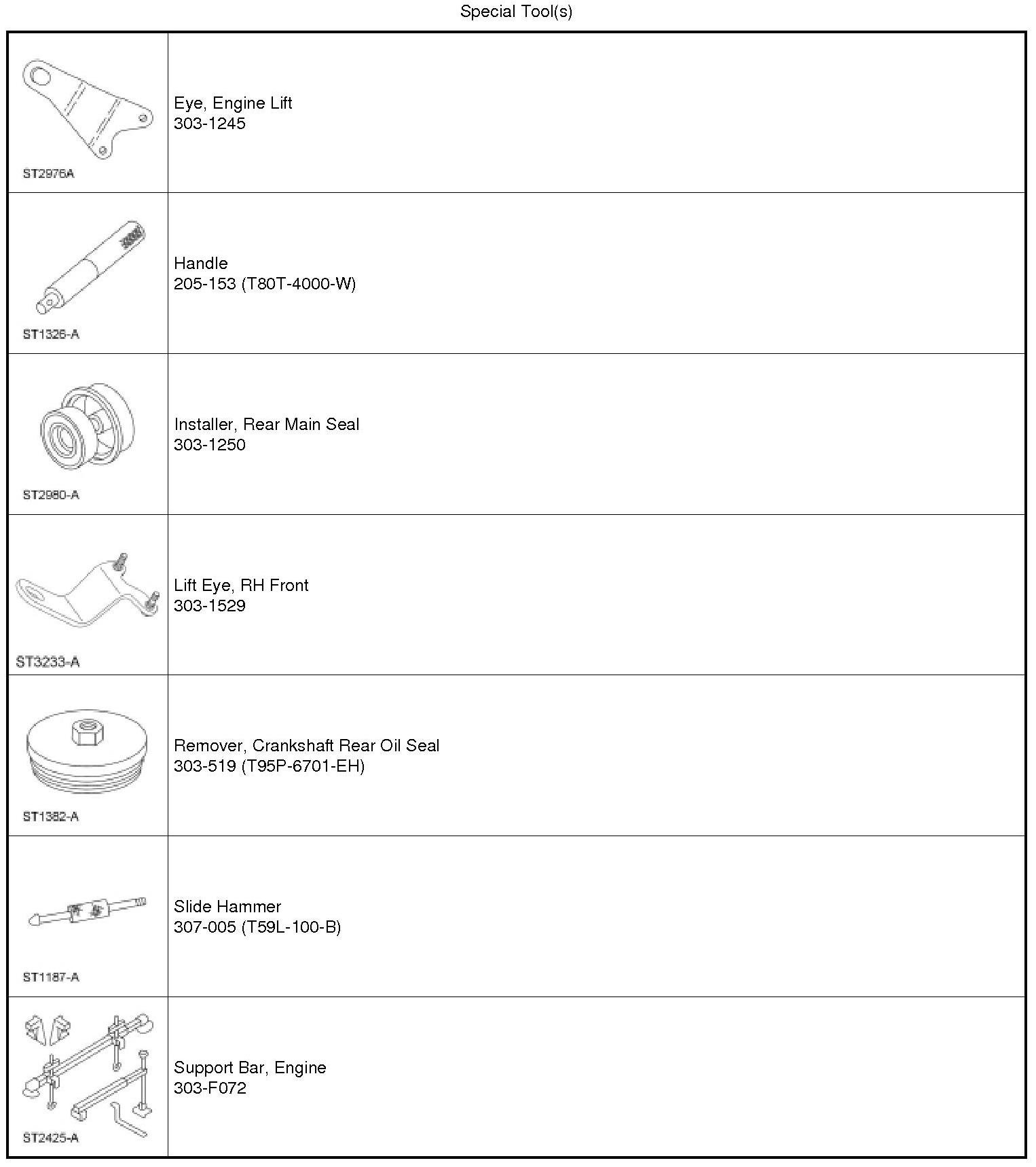
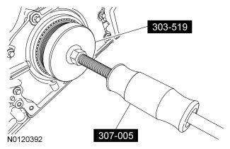
29. Using the Crankshaft Rear Oil Seal Remover and Slide Hammer, remove and discard the crankshaft rear seal.
30. Remove the 8 crankshaft rear seal retainer bolts.
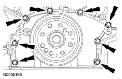
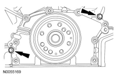
31. Using the 2 M6 oil pan bolts, install the bolts (finger-tight) into the 2 threaded holes in the crankshaft rear seal retainer.
- Alternately tighten the 2 bolts one turn at a time until the crankshaft rear seal retainer-to-cylinder block seal is released.
- Remove the crankshaft rear seal retainer.
32. NOTICE: Only use a 3M(TM) Roloc(R) Bristle Disk (2-in white, part number 07528) to clean the crankshaft real seal retainer plate and oil pan. Do not use metal scrapers, wire brushes or any other power abrasive disk to clean. These tools cause scratches and gouges that make leak paths.
Clean the crankshaft real seal retainer plate and engine oil pan using a 3M(TM) Roloc(R) Bristle Disk (2-in white, part number 07528) in a suitable tool turning at the recommended speed of 15,000 rpm.
- Thoroughly wash the crankshaft real seal retainer plate and oil pan to remove any foreign material, including any abrasive particles created during the cleaning process.
33. NOTICE: Do not use wire brushes, power abrasive discs or 3M(TM) Roloc(R) Bristle Disk (2-in white, part number 07528) to clean the sealing surfaces. These tools cause scratches and gouges that make leak paths. They also cause contamination that causes premature engine failure. Remove all traces of the gasket.
Clean the sealing surfaces of the cylinder block and engine front cover in the following sequence.
1. Remove any large deposits of silicone or gasket material.
2. Apply silicone gasket remover and allow to set for several minutes.
3. Remove the silicone gasket remover. A second application of silicone gasket remover may be required if residual traces of silicone or gasket material remain.
4. Apply metal surface prep to remove any remaining traces of oil and to prepare the surfaces to bond. Do not attempt to make the metal shiny. Some staining of the metal surfaces is normal.
Installation
1. NOTICE: Failure to use Motorcraft(R) High Performance Engine RTV Silicone may cause the engine oil to foam excessively and result in serious engine damage.
NOTE: The crankshaft rear seal retainer must be installed and the bolts tightened within 4 minutes of sealant application.
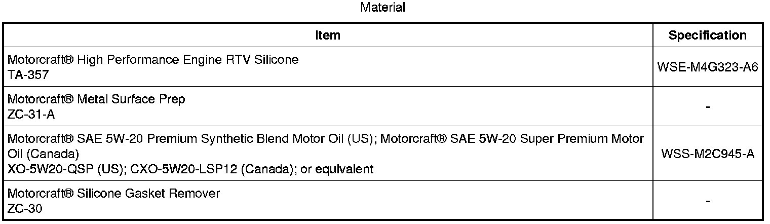
Apply a 3 mm (0.11 in) bead of Motorcraft(R) High Performance Engine RTV Silicone to the sealing surface of the crankshaft rear seal retainer.
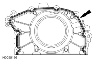
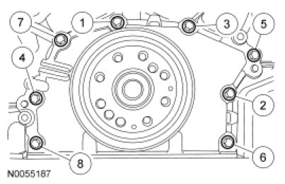
2. Install the rear seal retainer and the 8 bolts in the sequence shown.
- Tighten in the sequence shown to 10 Nm (89 lb-in).
3. NOTE: Lubricate the seal lips and bore with clean engine oil prior to installation.
Position the Rear Main Seal Installer onto the end of the crankshaft and slide a new crankshaft rear seal onto the tool.
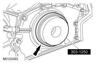
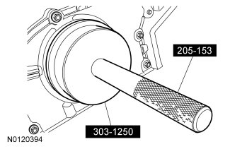
4. Using the Rear Main Seal Installer and Handle, install the new crankshaft rear seal.
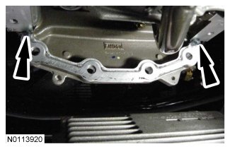
5. Apply a 5.5 mm (0.21 in) bead of Motorcraft(R) High Performance Engine RTV Silicone to the 2 engine front cover-to-cylinder block joint areas on the sealing surface of the oil pan.
6. NOTICE: Failure to use Motorcraft(R) High Performance Engine RTV Silicone may cause the engine oil to foam excessively and result in serious engine damage.
NOTE: The oil pan and the 4 specified bolts must be installed and the oil pan aligned to the cylinder block within 4 minutes of sealant application. Final tightening of the oil pan bolts must be carried out within 60 minutes of sealant application.
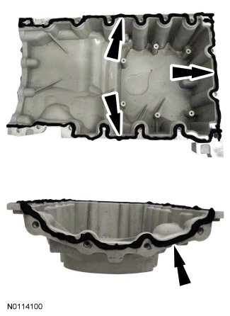
Apply a 3 mm (0.11 in) bead of Motorcraft(R) High Performance Engine RTV Silicone to the sealing surface of the oil pan-to-engine block and to the oil pan-to-engine front cover mating surface.
7. Apply a 5.5 mm (0.21 in) bead of Motorcraft(R) High Performance Engine RTV Silicone to the 2 crankshaft seal retainer plate-to-cylinder block joint areas on the sealing surface of the oil pan.
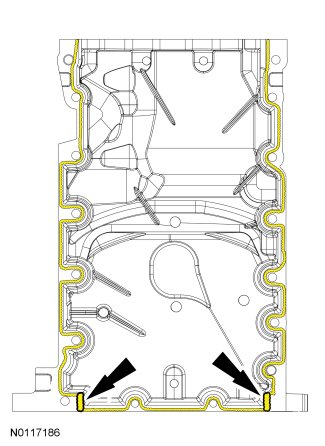
8. NOTE: The oil pan and the 4 specified bolts must be installed within 4 minutes of the start of sealant application.
NOTE: Keep the oil pan as close as possible to the transmission while installing, then slide forward towards the engine front cover to prevent wiping off of the sealant.
Install the oil pan and bolts 10, 11, 13 and 14 finger tight.
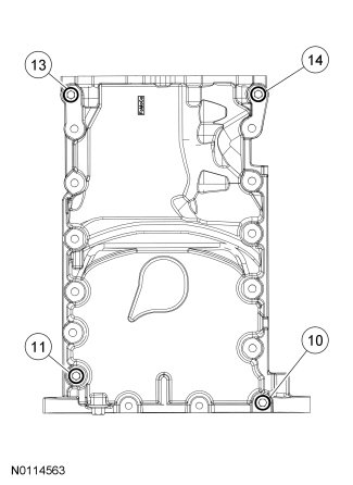
9. Install the 4 lower engine front cover bolts finger tight.
10. Laterally align the oil pan to the block. Make sure the oil pan is flush with the block at these 2 points.
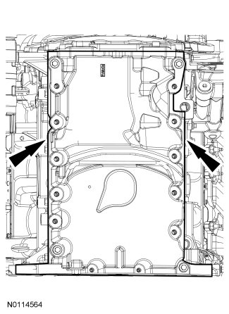
11. Tighten bolts 10, 11, 13 and 14 in the sequence shown to 3 Nm (27 lb-in).
12. Install the remaining oil pan bolts and tighten in the sequence shown.
- Tighten bolts 1-9 and 11-14 to 20 Nm (177 lb-in), then rotate an additional 45 degrees.
- Tighten bolts 15 and 16 to 10 Nm (89 lb-in), then rotate an additional 45 degrees.
- Tighten bolt 10 to 20 Nm (177 lb-in), then rotate an additional 90 degrees.
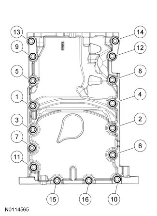
13. Tighten the 4 lower engine front cover bolts to 24 Nm (18 lb-ft).
14. NOTE: RH shown, LH similar.
Using the adjustable jackstand, raise the subframe and install the 4 front subframe nuts finger tight.
15. NOTE: RH shown, LH similar.
Align the subframe and install the 4 rear subframe bolts with the reference marks made during removal.
- Tighten to 115 Nm (85 lb-ft).
16. NOTE: RH shown, LH similar.
Tighten the 4 front subframe nuts to 115 Nm (85 lb-ft).
17. Connect the steering shaft and install the steering shaft pinch bolt.
- Tighten to 47 Nm (35 lb-ft).
18. Connect the 2 EPAS electrical connectors.
19. Attach the 2 EPAS wiring harness pin-type retainers.
20. NOTE: RH shown, LH similar.
Install the crossmember brace and the 6 bolts (2 shown).
- Tighten to 65 Nm (48 lb-ft).
21. NOTE: RH shown, LH similar.
Tighten the 2 nuts for the crossmember brace to 65 Nm (48 lb-ft).
22. Install the lower air deflector and the 9 bolts.
- Tighten to 5 Nm (44 lb-in).
23. Install the RH radiator support bracket and the 2 bolts.
- Tighten to 10 Nm (89 lb-in).
24. Install the radiator sight shield and the 8 pin-type retainers.
25. Position the generator wiring harness bracket on the rear LH valve cover stud bolt and install the nut.
- Tighten to 10 Nm (89 lb-in).
26. NOTE: RH shown, LH similar.
Install the RH and LH engine mount bracket-to-engine mount nuts.
- Tighten to 63 Nm (46 lb-ft).
27. Install the oil level indicator.
28. Install the engine-to-transmission spacer plate.
29. Install the crankshaft sensor ring.
30. Install the flexplate or flywheel. For additional information, refer to Flexplate Removal and Replacement or Flywheel Flywheel.
31. Install the CKP sensor. For additional information, refer to Electronic Engine Controls Exploded Views.
32. Install the 2 steering column dash boot bearing nuts.
- Tighten to 9 Nm (80 lb-in).
33. Fill the engine with clean engine oil.
34. After completing the repairs, use the scan tool to perform the Misfire Monitor Neutral Profile Correction procedure following the on-screen instructions.