Part 2
Camshaft
WARNING: Do not smoke, carry lighted tobacco or have an open flame of any type when working on or near any fuel-related component. Highly flammable mixtures are always present and may be ignited. Failure to follow these instructions may result in serious personal injury.
NOTICE: During engine repair procedures, cleanliness is extremely important. Any foreign material, including any material created while cleaning gasket surfaces that enters the oil passages, coolant passages or the oil pan, may cause engine failure.
41. NOTICE: Do not allow the intermediate shaft to rotate while it is disconnected from the gear or damage to the clockspring can occur. If there is evidence that the intermediate shaft has rotated, the clockspring must be removed and recentered. For additional information, refer to Restraints and Safety Systems &/or Air Bag Systems.
Remove and discard the steering intermediate shaft bolt.
- Separate the steering intermediate shaft from the steering gear.
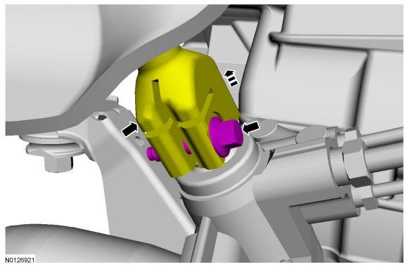
42. NOTE: RH shown, LH similar.
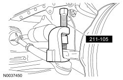
Remove and discard the cotter pins and tie-rod end nuts.
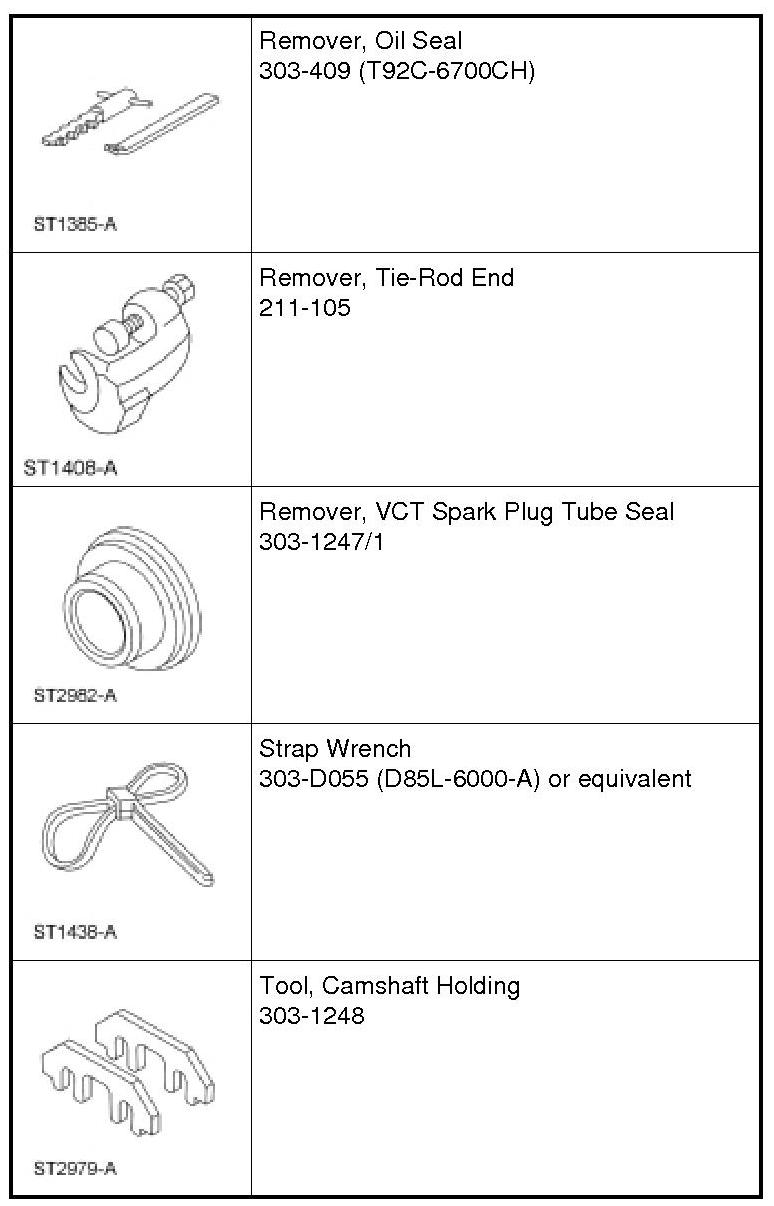
- Using the Tie-Rod End Remover, separate the tie-rod ends from the wheel knuckles.
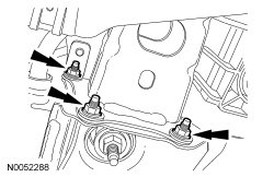
43. Remove the 3 RH subframe-to-lower bumper nuts.
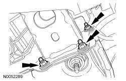
44. Remove the 3 LH subframe-to-lower bumper nuts and separate the lower bumper from the subframe.
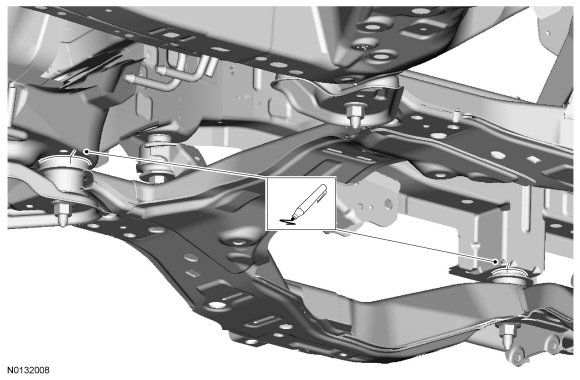
45. Mark the relationship of the front subframe to the underbody at the mounting locations.
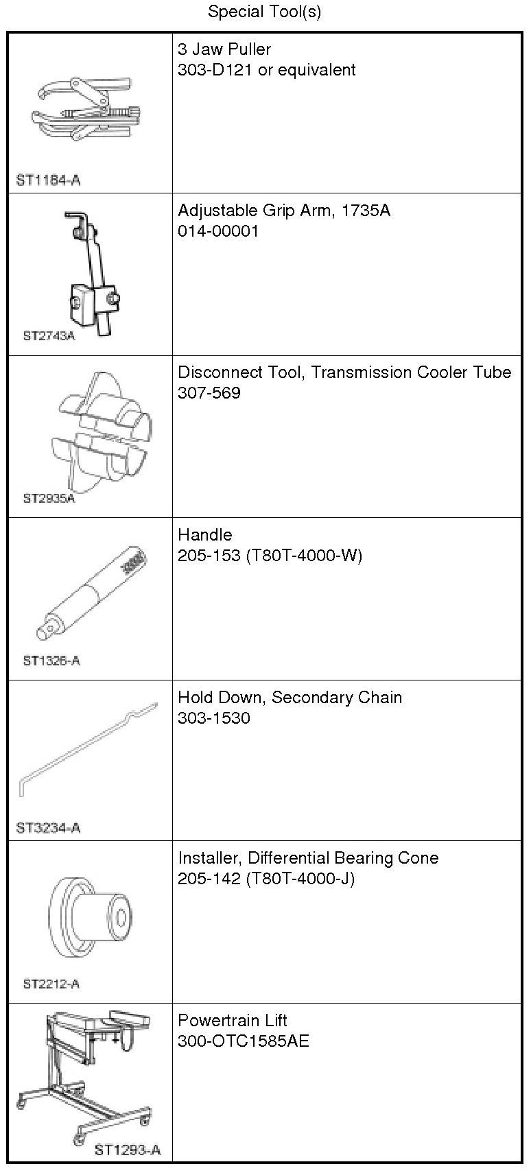
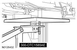
46. Position the Powertrain Lift under the subframe assembly.
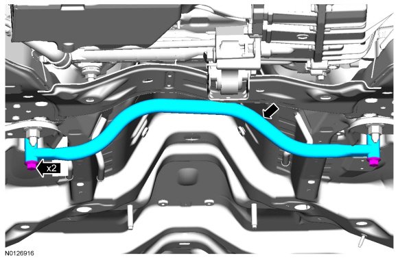
47. Remove the 2 bolts and the subframe brace.
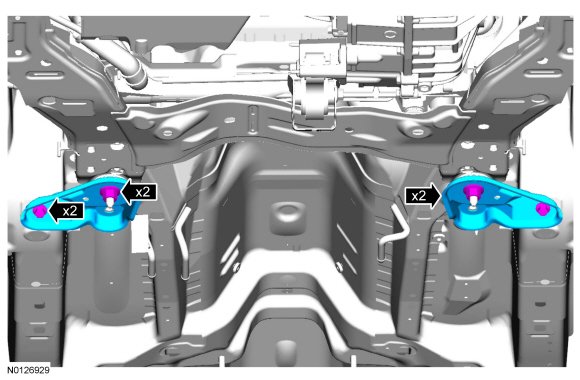
48. Remove the 2 nuts, 2 bolts and the 2 subframe support brackets.
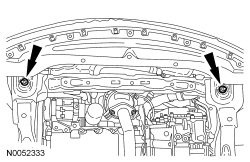
49. Remove the 2 front subframe nuts.
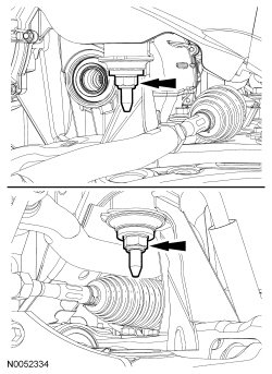
50. Remove the 2 middle subframe nuts.
51. Using the Powertrain Lift, lower the subframe assembly from the vehicle.
52. NOTICE: The fuel and vapor tube assembly clip must remain attached to the transaxle case stud during engine removal. Failure to follow these instructions can result in damage to the fuel and vapor tube assembly.
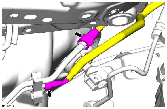
Disconnect the fuel supply tube and Evaporative Emission (EVAP) tube quick connect couplings.
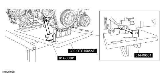
53. NOTE: Position a block of wood under the transaxle.
Install the Powertrain Lift and Adjustable Grip Arms.
54. Remove the transaxle support insulator through bolt and nut.
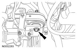
55. Remove the 3 nuts, the bolt and the transaxle support insulator bracket.
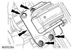
56. Remove the nut, bolt and engine mount brace.
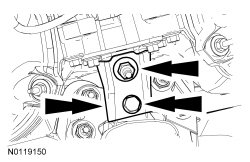
57. Remove the 4 engine mount nuts.
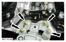
58. Remove the 3 bolts and the engine mount.
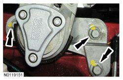
59. Lower the engine and transaxle assembly from the vehicle.
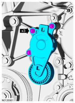
60. Remove the 3 bolts and the accessory drive belt tensioner.
61. Using the Strap Wrench, remove the crankshaft pulley bolt and washer.
- Discard the bolt.
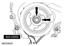
62. Using the 3 Jaw Puller, remove the crankshaft pulley.
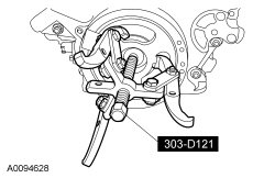
63. Using the Oil Seal Remover, remove and discard the crankshaft front seal.
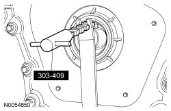
64. Remove the crankcase vent tube.
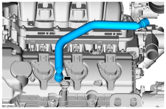
65. Disconnect the 3 LH coil-on-plug electrical connectors.
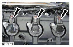
66. Remove the 3 bolts and the 3 LH -coil-on-plugs.
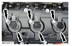
67. Detach the wiring harness connector pin-type retainer from the LH valve cover.
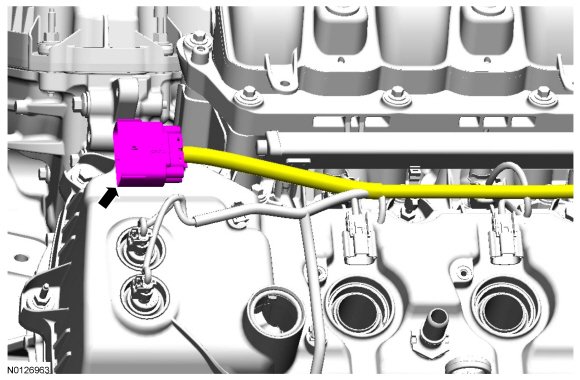
68. Detach the 2 wiring harness retainers from the LH valve cover stud bolts and position the harness aside.
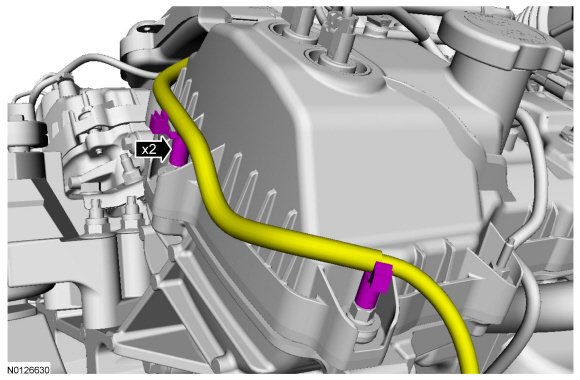
69. Disconnect the 2 Variable Camshaft Timing (VCT) oil control solenoid electrical connectors.
- Detach the wiring harness pin-type retainer.
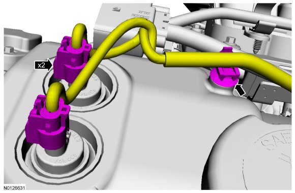
70. Detach the 2 wiring harness pin-type retainers.
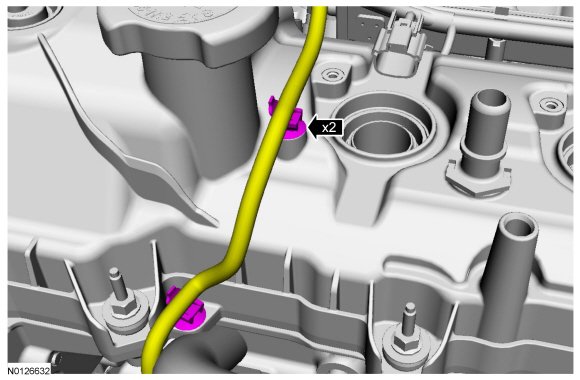
71. Disconnect the LH Heated Oxygen Sensor (HO2S) electrical connector.
- Detach the wiring harness connector pin-type retainer from the LH valve cover.
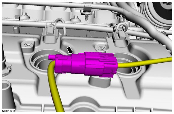
72. Disconnect the 3 fuel injector electrical connectors.
- Detach the 2 wiring harness retainers from the LH valve cover stud bolts.
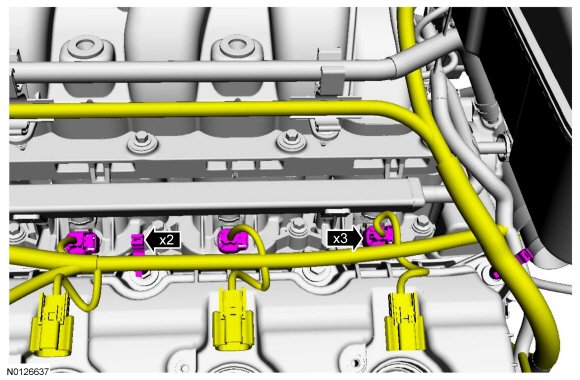
73. Detach the 2 wiring harness retainers and position the harness aside.
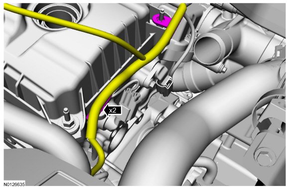
74. NOTICE: While removing the valve cover do not apply excessive force to the Variable Camshaft Timing (VCT) oil control solenoid or damage may occur.
NOTICE: If the Variable Camshaft Timing (VCT) oil control solenoid sticks to the VCT (Variable Camshaft Timing) seal, carefully wiggle the valve cover until the bond breaks free or damage to the VCT (Variable Camshaft Timing) seal and VCT (Variable Camshaft Timing) oil control solenoid may occur.
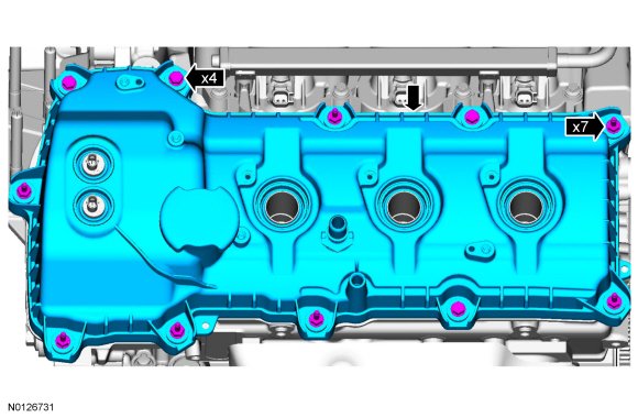
Loosen the 4 bolts and 7 stud bolts.
- Remove the LH valve cover.
- Discard the gasket.
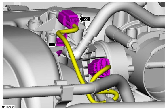
75. Disconnect the Evaporative Emission (EVAP) canister vent solenoid and throttle body electrical connectors.
- Detach the wiring harness pin-type retainer.
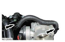
76. Disconnect the EVAP (Evaporative Emission) vapor tube from the EVAP (Evaporative Emission) canister vent solenoid.
- Detach the EVAP (Evaporative Emission) tube retainer.
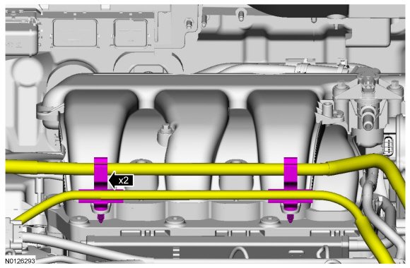
77. Detach the 2 wiring harness/coolant tube retainers from the upper intake manifold.
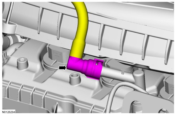
78. Disconnect the crankcase ventilation hose from the Positive Crankcase Ventilation (PCV) valve.
79. Remove the upper intake manifold support bracket bolt.
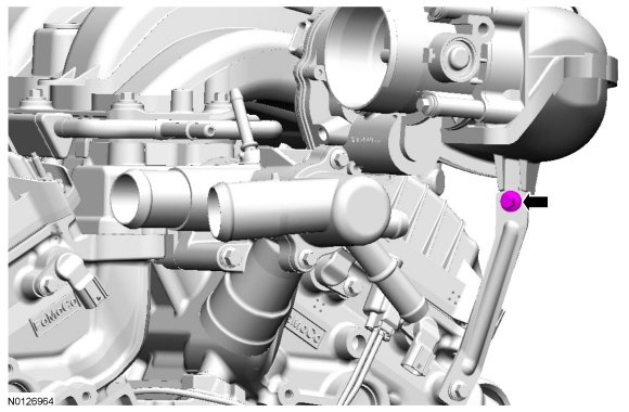
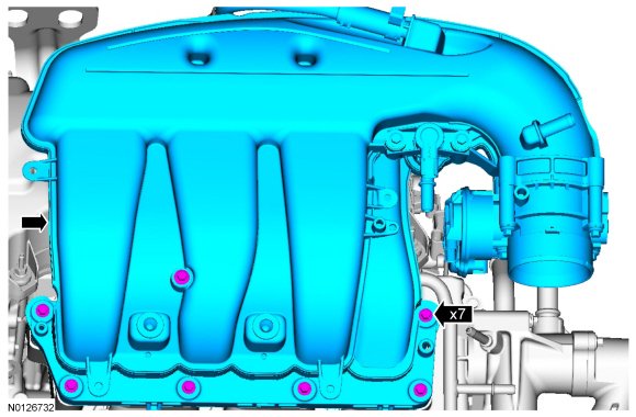
80. Remove the 7 bolts and the upper intake manifold.
- Remove and discard the gasket.
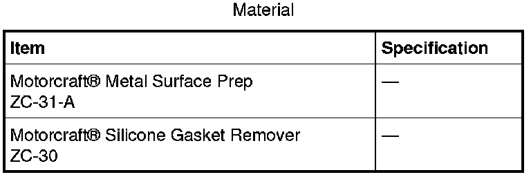
- Clean and inspect all of the sealing surfaces of the upper and lower intake manifold.