Pinpoint Test D: DTCs B106E, B106F, B1217 and B1218
Tire Pressure Monitoring System
Pinpoint Tests
Pinpoint Test D: DTCs B106E, B106F, B1217 and B1218
Refer to Wiring Diagram Set 118, Tire Pressure Monitoring System (TPMS) for schematic and connector information. Diagrams By Number
Normal Operation
The Tire Pressure Monitoring System (TPMS)/Vehicle Security Module (VSM) will use the horn as a feedback signal during TPMS sensor training and activation. To do this, the TPMS/VSM sends a ground signal to the Generic Electronic Module (GEM) along circuit 9-WA6 (BN). When the GEM receives this ground signal it will activate the horn relay and sound the horn. The TPMS monitors circuit 9-WA6 (BN) for shorts (to voltage and ground) and opens. If one of these conditions is detected, the appropriate DTC will be set. The module utilizes a Field-Effect Transistor (FET) (in place of a fuse) to protect itself during a short circuit condition, the FET is also known as a solid state driver.
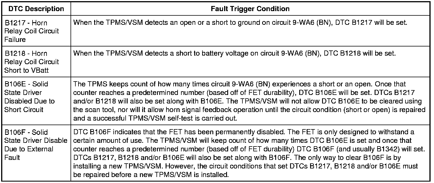
This pinpoint test is intended to diagnose the following:
- Wiring, terminals or connectors
- TPMS/VSM
- GEM module
PINPOINT TEST D: DTCs B106E, B106F, B1217 AND B1218
-------------------------------------------------
D1 CHECK THE HORN OPERATION
NOTICE: If DTC B106F is present, the fault condition must be corrected prior to installing a new Tire Pressure Monitoring System (TPMS)/Vehicle Security Module (VSM). Failure to correct the fault condition first may cause damage to the new TPMS/VSM, resulting in a repeat repair.
- Push the horn pad.
- Does the horn sound?
Yes
GO to D2.
No
GO to Horn to diagnose the horn.
-------------------------------------------------
D2 CHECK THE TPMS HORN OUTPUT USING THE HORN RELAY ACTIVE COMMAND
- Connect the scan tool.
- Ignition ON.
- Enter the following diagnostic mode on the scan tool: DataLogger - TPMS/VSM.
- Toggle the horn relay active command ON.
- Does the horn sound?
Yes
TOGGLE the active command OFF. The condition to set the code is not present. INSPECT the TPMS/VSM connector for corrosion, spread terminals and pushed-out terminals. REPAIR the connector as necessary.
No
TOGGLE the active command OFF. GO to D3.
-------------------------------------------------
D3 CHECK THE GEM FOR A SHORT TO VOLTAGE
- Ignition OFF.
- Disconnect: TPMS/VSM C2409B.
- Ignition ON.
- Measure the voltage between TPMS/ VSM connector C2409B-9, circuit 9-WA6 (BN), harness side and ground.
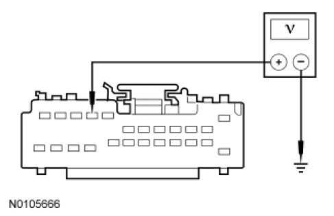
- Is any voltage present?
Yes
GO to D4.
No
GO to D5.
-------------------------------------------------
D4 CHECK THE TPMS/VSM HORN OUTPUT CIRCUIT FOR A SHORT TO VOLTAGE
- Ignition OFF.
- Disconnect: GEM C102B.
- Ignition ON.
- Measure the voltage between TPMS/ VSM connector C2409B-9, circuit 9-WA6 (BN), harness side and ground.
- Is any voltage present?
Yes
REPAIR circuit 9-WA6 (BN). GO to D8.
No
GO to D10.
-------------------------------------------------
D5 CHECK THE GEM FOR A SHORT TO GROUND
- Ignition OFF.
- Measure the resistance between TPMS/ VSM C2409B-9, circuit 9-WA6 (BN), harness side and ground.
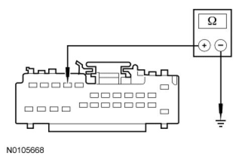
- Is the resistance greater than 10,000 ohms?
Yes
GO to D7.
No
GO to D6.
-------------------------------------------------
D6 CHECK THE TPMS/VSM HORN OUTPUT CIRCUIT FOR A SHORT TO GROUND
- Disconnect: GEM C102B.
- Measure the resistance between TPMS/ VSM C2409B-9, circuit 9-WA6 (BN), harness side and ground.
- Is the resistance greater than 10,000 ohms?
Yes
GO to D10.
No
REPAIR circuit 9-WA6 (BN). GO to D8.
-------------------------------------------------
D7 CHECK THE TPMS/VSM HORN OUTPUT CIRCUIT FOR AN OPEN
- Disconnect: GEM C102B.
- Measure the resistance between TPMS/VSM C2409B-9, circuit 9-WA6 (BN), harness side and GEM C102B-15, circuit 9-WA6 (BN), harness side.
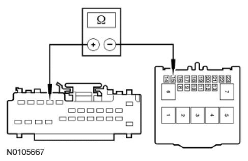
- Is the resistance less than 5 ohms?
Yes
GO to D9.
No
GO to D8.
-------------------------------------------------
D8 CHECK THE TPMS/VSM DTCs
- Review the DTCs retrieved during Inspection and Verification.
- Are DTCs B106E and/or B106F present?
Yes
If DTC B106F is present, INSTALL a new TPMS/VSM. REFER to Tire Pressure Monitoring System (TPMS) Module Service and Repair. If DTC B106E is present, CONNECT all connectors, CYCLE the ignition switch, CLEAR the DTCs and CARRY OUT a TPMS/VSM self-test.
No
GO to D9.
-------------------------------------------------
D9 CHECK TPMS/VSM OPERATION
- Check TPMS/VSM connector C2409B for:
- corrosion.
- pushed-out pins.
- spread terminals.
- Connect: TPMS/VSM C2409B.
- Connect: GEM C102B.
- Make sure the connector is seated correctly, then operate the system and verify the concern is still present.
- Is the concern still present?
Yes
INSTALL a new TPMS/VSM. REFER to Tire Pressure Monitoring System (TPMS) Module Service and Repair. CARRY OUT a TPMS/VSM self-test.
No
The system is operating correctly at this time. The concern may have been caused by a loose or corroded connector. CLEAR the DTCs. REPEAT the self-test.
-------------------------------------------------
D10 CHECK GEM OPERATION
- CHECK GEM C102B for:
- corrosion.
- pushed-out pins.
- spread terminals.
- Connect: GEM C102B.
- Connect: TPMS/VSM C2409B.
- Make sure the connector is seated correctly, then operate the system and verify the concern is still present.
- Is the concern still present?
Yes
INSTALL a new GEM. REFER to Body Control Systems. CARRY OUT a TPMS/VSM self-test.
No
The system is operating correctly at this time. The concern may have been caused by a loose or corroded connector. CLEAR the DTCs. REPEAT the TPMS/VSM self-test.
-------------------------------------------------