Camshaft - LH
Camshaft - LH

Removal
NOTICE: The camshaft procedure must be followed exactly or damage to the valves and pistons will result.
1. Remove the LH valve cover. For additional information, refer to Valve Cover - LH Valve Cover - LH.
2. NOTICE: Damage to the camshaft phaser and sprocket assembly will occur if mishandled or used as a lifting or leveraging device.
Loosen and back off the LH camshaft phaser and sprocket bolt one full turn.
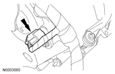
3. Disconnect the LH Camshaft Position (CMP) sensor electrical connector.
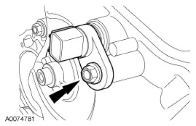
4. Remove the LH CMP sensor and the bolt.
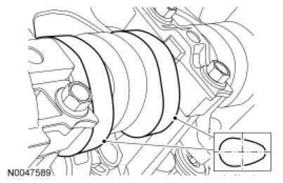
5. Rotate the crankshaft clockwise until the No. 5 cylinder camshaft exhaust lobe opens the valve and the 2 intake lobes are in the 3 o'clock position as shown.
6. Remove only the 3 camshaft roller followers shown in the illustration.
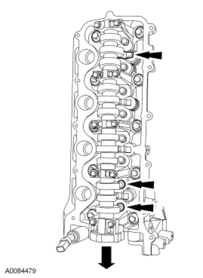
7. NOTICE: The camshaft roller followers must be installed in their original locations. Record camshaft roller follower locations. Failure to follow these instructions may result in engine damage.
NOTE: Do not allow the valve keepers to fall off the valve or the valve may drop into the cylinder. If a valve drops into the cylinder, the cylinder head must be removed. For additional information, refer to Cylinder Head Cylinder Head - Removal.
NOTE: It may be necessary to push the valve down while compressing the spring.
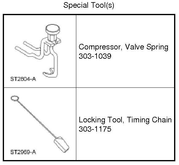
Using the Valve Spring Compressor, remove only the 3 designated camshaft roller followers from the previous step.
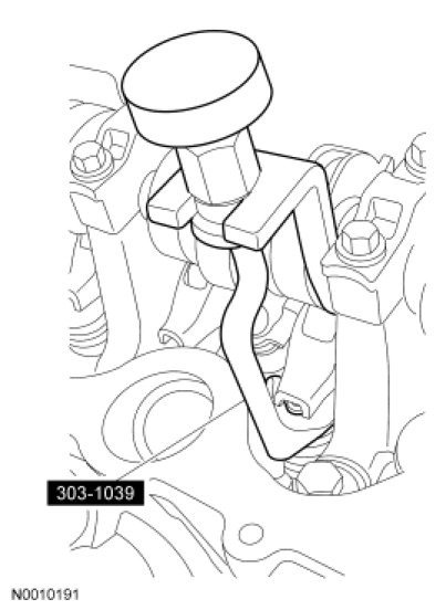
8. NOTICE: The crankshaft cannot be moved once set or engine damage may occur.
Rotate the crankshaft a half turn clockwise, as viewed from the front, positioning the No. 5 cylinder camshaft exhaust lobe at the 11 o'clock position as shown.
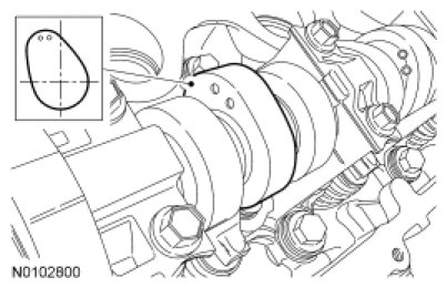
9. NOTICE: Engine is not freewheeling. Camshaft procedure must be followed exactly or damage to valves and pistons will result.
NOTE: The Timing Chain Locking Tool must be installed square to the timing chain and the engine block.
NOTE: Engine front cover removed from art for clarity.
Install the Timing Chain Locking Tool in the LH timing chain as shown.
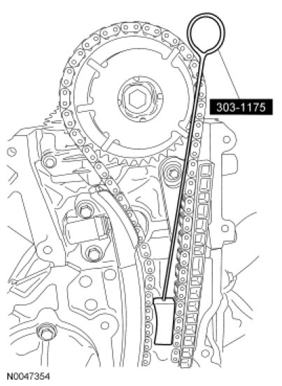
10. NOTICE: Do not remove the Timing Chain Locking Tool at any time during assembly. If the Timing Chain Locking Tool is removed or out of placement, the engine front cover must be removed and the engine must be retimed. For additional information, refer to Timing Drive Components Removal and Replacement. Failure to follow this instruction can result in damage to the valves and pistons.
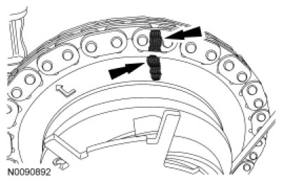
NOTICE: The timing chain must be installed in its original position onto the camshaft phaser and sprocket using the scribed marks, or damage to valves and pistons will result.
NOTE: RH shown, LH similar.
Scribe a location mark on the timing chain and the camshaft phaser and sprocket assembly.
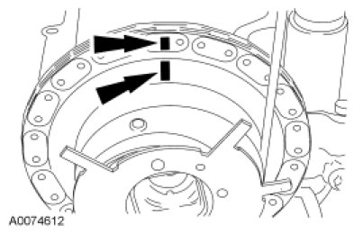
11. NOTICE: Remove the front thrust camshaft bearing cap straight upward from the bearing towers or the bearing cap may be damaged from side loading.
Remove the 2 bolts and the LH cylinder head camshaft front bearing cap.
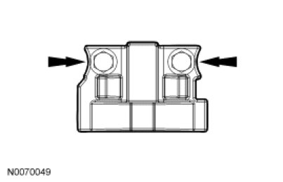
12. NOTICE: The camshaft bearing caps must be installed in their original locations. Record camshaft bearing cap locations. Failure to follow these instructions may result in engine damage.
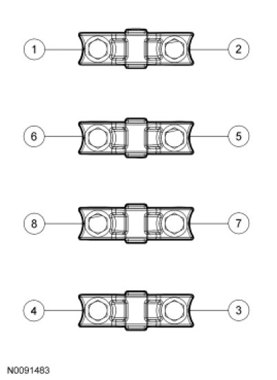
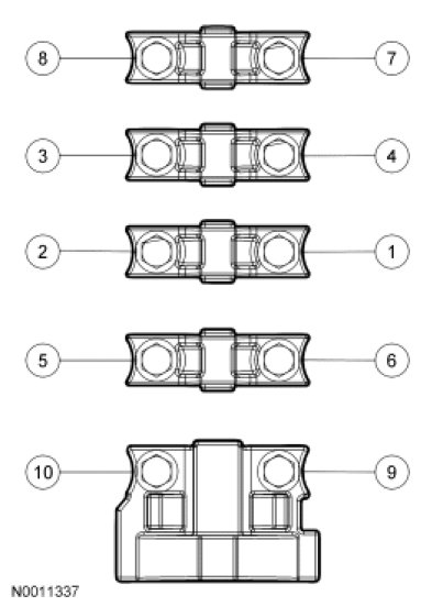
Remove the remaining bolts in the sequence shown and remove the LH cylinder head camshaft bearing caps.
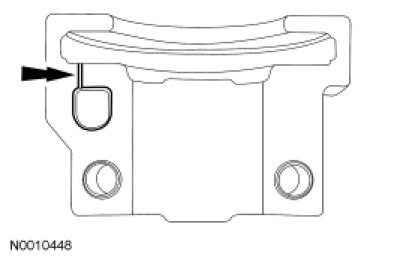
13. Clean and inspect the LH camshaft bearing caps.
- The camshaft front thrust bearing cap contains an oil metering groove. Make sure the groove is free of foreign material.
14. NOTICE: Damage to the camshaft phaser and sprocket assembly will occur if mishandled or used as a lifting or leveraging device.
NOTICE: Only use hand tools to remove the camshaft phaser and sprocket bolt or damage may occur to the camshaft or camshaft phaser and sprocket.
NOTICE: Do not remove the Timing Chain Locking Tool at any time during assembly. If the Timing Chain Locking Tool is removed or out of placement, the engine front cover must be removed and the engine must be retimed. For additional information, refer to Timing Drive Components Removal and Replacement. Failure to follow this instruction can result in damage to the valves and pistons.
Remove the bolt and the camshaft phaser and sprocket assembly from the camshaft.
- Discard the bolt and washer.
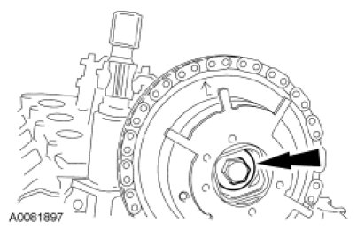
15. Remove the camshaft.
16. Remove and inspect the camshaft phaser and sprocket for damage. For additional information, refer to Engine.
Installation
1. NOTE: Do not allow the camshaft roller followers to move out of position when installing the camshaft.
Lubricate the camshaft and camshaft journals with clean engine oil and install the camshaft.
2. NOTICE: Do not remove the Timing Chain Locking Tool at any time during assembly. If the Timing Chain Locking Tool is removed or out of placement, the engine front cover must be removed and the engine must be retimed. For additional information, refer to Timing Drive Components Removal and Replacement. Failure to follow this instruction can result in damage to the valves and pistons.
NOTICE: The timing chain must be installed in its original position onto the camshaft phaser and sprocket using the scribed marks, or damage to valves and pistons will result.
NOTE: If replacement of the camshaft phaser and sprocket is necessary, transfer the scribe mark to the new camshaft phaser and sprocket.
Position the camshaft phaser and sprocket into the timing chain with the timing chain scribe marks in alignment.
3. NOTICE: Do not remove the Timing Chain Locking Tool at any time during assembly. If the Timing Chain Locking Tool is removed or out of placement, the engine front cover must be removed and the engine must be retimed. For additional information, refer to Timing Drive Components Removal and Replacement.
NOTICE: Damage to the camshaft phaser and sprocket assembly will occur if mishandled or used as a lifting or leveraging device.
Install the camshaft phaser and sprocket assembly onto the camshaft and install a new camshaft phaser and sprocket bolt finger-tight.
4. Install the camshaft bearing caps in their original locations.
- Lubricate the camshaft bearing caps with clean engine oil.
- Position the front camshaft bearing cap.
- Position the remaining camshaft bearing caps.
- Install the bolts loosely.
5. Tighten the bolts in the sequence shown.
- Tighten to 10 Nm (89 lb-in).
6. NOTE: Engine front cover removed from art for clarity.
Remove the Timing Chain Locking Tool.
7. Rotate the crankshaft a half turn counterclockwise until the No. 5 cylinder camshaft exhaust lobe opens the valve and the 2 intake lobes are in the 3 o'clock position as shown.
8. NOTE: Do not allow the valve keepers to fall off of the valve or the valve may drop into the cylinder. If a valve drops into the cylinder, the cylinder head must be removed. For additional information, refer to Cylinder Head Cylinder Head - Removal.
NOTE: It may be necessary to push the valve down while compressing the spring.
Using the Valve Spring Compressor, install the 3 originally removed camshaft roller followers.
9. Install the CMP sensor and the bolt.
- Tighten to 10 Nm (89 lb-in).
10. Connect the CMP electrical connector.
11. NOTICE: Only use hand tools to install the camshaft phaser and sprocket assembly or damage may occur to the camshaft or camshaft phaser and sprocket.
NOTICE: Damage to the camshaft phaser and sprocket assembly will occur if mishandled or used as a lifting or leveraging device.
Tighten the camshaft phaser and sprocket bolt in 2 stages:
- Stage 1: Tighten to 40 Nm (30 lb-ft).
- Stage 2: Tighten an additional 90 degrees.
12. Install the LH valve cover. For additional information, refer to Valve Cover - LH Valve Cover - LH.