Pinpoint Test I: The Washer Pump Is Inoperative - TAURUS X
- I1 CHECK CIRCUIT CRW14 (BU/WH) FOR GROUND
- Disconnect: Washer Pump Motor C137
- Key in ON position.
- Measure the resistance between washer pump motor C137-2, circuit CRW14 (BU/WH) harness side and ground.
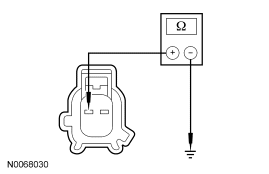 Courtesy of FORD MOTOR CO.
- Is the resistance less than 5 ohms?
- YES
: Go to I3.
- NO
: Go to I2.
- I2 CHECK CIRCUIT CRW14 (BU/WH) FOR AN OPEN
- Key in OFF position.
- Disconnect: Windshield Wiper Motor C125
- Measure the resistance between windshield wiper motor C125-7, circuit CRW14 (BU/WH), harness side and washer pump motor C137-2, circuit CRW14 (BU/WH) harness side.
 Courtesy of FORD MOTOR CO.
- Is the resistance less than 5 ohms?
- YES
: Go to I14.
- NO
: REPAIR the circuit. TEST the system for normal operation.
- I3 CHECK CIRCUIT GD120 (BK/GN) FOR GROUND
- Measure the resistance between washer pump motor C137-1, circuit GD120 (BK/GN) harness side and ground.
 Courtesy of FORD MOTOR CO.
- Is the resistance less than 5 ohms?
- YES
: Go to I6.
- NO
: Go to I4.
- I4 CHECK CIRCUIT GD120 (BK/GN) FOR AN OPEN
- Key in OFF position.
- Disconnect: Rear Window Wiper Motor C476
- Measure the resistance between rear window wiper motor C476-6, circuit GD120 (BK/GN), harness side and washer pump motor C137-1, circuit GD120 (BK/GN) harness side.
 Courtesy of FORD MOTOR CO.
- Is the resistance less than 5 ohms?
- YES
: Go to I5.
- NO
: REPAIR the circuit. TEST the system for normal operation.
- I5 CHECK CIRCUIT GD133 (BK) FOR AN OPEN
- Measure the resistance between rear window wiper motor C476-5, circuit GD133 (BK), harness side and ground.
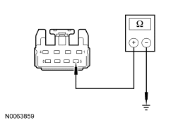 Courtesy of FORD MOTOR CO.
- Is the resistance less than 5 ohms?
- YES
: Go to I15.
- NO
: REPAIR the circuit. TEST the system for normal operation.
- I6 CHECK CIRCUIT CRW14 (BU/WH) FOR VOLTAGE
- Key in ON position.
- Measure the voltage between washer pump motor C137-2, circuit CRW14 (BU/WH) harness side and ground while depressing the multi-function switch to the wash position.
 Courtesy of FORD MOTOR CO.
- Is the voltage greater than 10 volts?
- YES
: Go to I10.
- NO
: Go to I7.
- I7 CHECK CIRCUIT CRW14 (BU/WH) FOR A SHORT TO GROUND
- Key in OFF position.
- Disconnect: Windshield Wiper Motor C125
- Measure the resistance between washer pump motor C137-2, circuit CRW14 (BU/WH) harness side and ground.
Courtesy of FORD MOTOR CO.
- Is the resistance greater than 10,000 ohms?
- YES
: Go to I8.
- NO
: REPAIR the circuit. TEST the system for normal operation.
- I8 CHECK THE MULTI-FUNCTION SWITCH
- Disconnect: Multi-Function Switch C202
- Carry out the Multi-Function Switch Component Test. Refer to COMPONENT TESTING
article.
- Did the multi-function switch pass the component test?
- YES
: Go to I9.
- NO
: INSTALL a new multi-function switch. REFER to STEERING COLUMN SWITCHES
article. TEST the system for normal operation.
- I9 CHECK CIRCUIT CRW07 (GY/BN) FOR AN OPEN OR SHORT TO GROUND
- Measure the resistance between windshield wiper motor C125-12, circuit CRW07 (GY/BN) harness side and multi-function switch C202-10, circuit CRW07 (GY/BN) harness side; and between multi-function switch C202-10, circuit CRW07 (GY/BN) harness side and ground.
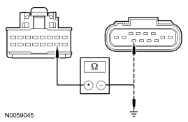 Courtesy of FORD MOTOR CO.
- Is the resistance less than 5 ohms between multi-function switch and wiper motor; and greater than 10,000 ohms between multi-function switch and ground?
- YES
: Go to I14.
- NO
: REPAIR the circuit. TEST the system for normal operation.
- I10 CHECK CIRCUIT GD120 (BK/GN) FOR VOLTAGE
- Measure the voltage between washer pump motor C137-1, circuit GD120 (BK/GN) harness side and ground while depressing the multi-function switch to the rear wash position.
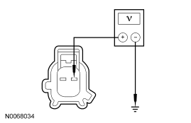 Courtesy of FORD MOTOR CO.
- Is the voltage greater than 10 volts?
- YES
: INSTALL a new washer pump. TEST the system for normal operation.
- NO
: Go to I11.
- I11 CHECK CIRCUIT GD120 (BK/GN) FOR A SHORT TO GROUND
- Key in OFF position.
- Disconnect: Rear Window Wiper Motor C476
- Measure the resistance between washer pump motor C137-1, circuit GD120 (BK/GN) harness side and ground.
Courtesy of FORD MOTOR CO.
- Is the resistance greater than 10,000 ohms?
- YES
: Go to I12.
- NO
: REPAIR the circuit. TEST the system for normal operation.
- I12 CHECK THE MULTI-FUNCTION SWITCH
- Disconnect: Multi-Function Switch C202
- Carry out the Multi-Function Switch Component Test. Refer to COMPONENT TESTING
article.
- Did the multi-function switch pass the component test?
- YES
: Go to I13.
- NO
: INSTALL a new multi-function switch. REFER to STEERING COLUMN SWITCHES
article. TEST the system for normal operation.
- I13 CHECK CIRCUIT CRW20 (GY/YE) FOR AN OPEN OR SHORT TO GROUND
- Measure the resistance between rear window wiper motor C476-7, circuit CRW20 (GY/YE) harness side and multi-function switch C202-14, circuit CRW20 (GY/YE) harness side; and between multi-function switch C202-14, circuit CRW20 (GY/YE) harness side and ground.
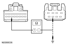 Courtesy of FORD MOTOR CO.
- Is the resistance less than 5 ohms between multi-function switch and wiper motor; and greater than 10,000 ohms between multi-function switch and ground?
- YES
: Go to I15.
- NO
: REPAIR the circuit. TEST the system for normal operation.
- I14 CHECK THE WINDSHIELD WIPER MOTOR
- Disconnect all wiper motor connectors.
- Check for:
- Connect all wiper motor connectors and make sure they seat correctly.
- Operate the system and verify the concern is still present.
- Is the concern still present?
- YES
: INSTALL a new windshield wiper motor. REFER to Wiper Motor - Windshield . TEST the system for normal operation.
- NO
: REPAIR the circuit. TEST the system for normal operation.
- I15 CHECK THE REAR WINDOW WIPER MOTOR
- Disconnect all wiper motor connectors.
- Check for:
- Connect all wiper motor connectors and make sure they seat correctly.
- Operate the system and verify the concern is still present.
- Is the concern still present?
- YES
: INSTALL a new rear window wiper motor. REFER to Wiper Motor - Rear Window . TEST the system for normal operation.
- NO
: REPAIR the circuit. TEST the system for normal operation.