Rear Drive Axle/Differential - Ford 8.8-Inch Ring Gear
Drive Pinion Flange
Removal
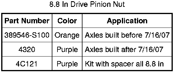
NOTICE: The color on the rear face of the drive pinion nut is critical to this repair. Use the same color new drive pinion nut for installation. If a new collapsible spacer is installed, install the nut in the kit or damage to the component may occur.
1. With the vehicle in NEUTRAL, position it on a hoist.
2. NOTE: The rear wheels and brake drums must be removed to prevent brake drag during drive pinion bearing preload adjustment.
Remove the rear wheel and tire.
3. Remove the rear brake drums.
4. NOTE: Index-mark the driveshaft flange and pinion flange for correct alignment during installation.
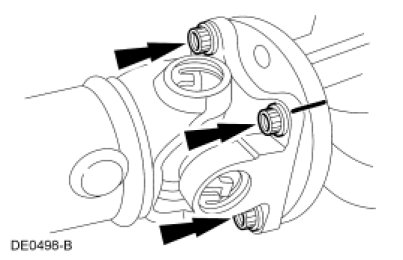
Remove the 4 driveshaft-to-pinion flange bolts.
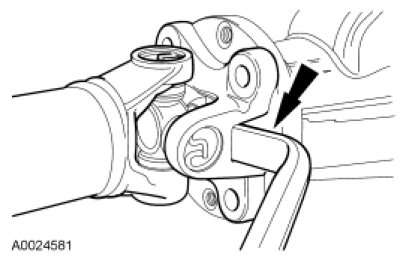
5. NOTICE: The driveshaft flange fits tightly on the rear axle pinion flange pilot. Never hammer on the driveshaft or any of its components to disconnect the driveshaft flange from the pinion flange. Pry only in the area shown with a suitable tool to disconnect the driveshaft flange from the pinion flange or damage to the component may occur.
Using a suitable tool as shown, disconnect the driveshaft flange from the rear axle pinion flange.
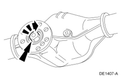
6. Install a Nm (lb-in) torque wrench on the nut and record the torque necessary to maintain rotation of the pinion through several revolutions.
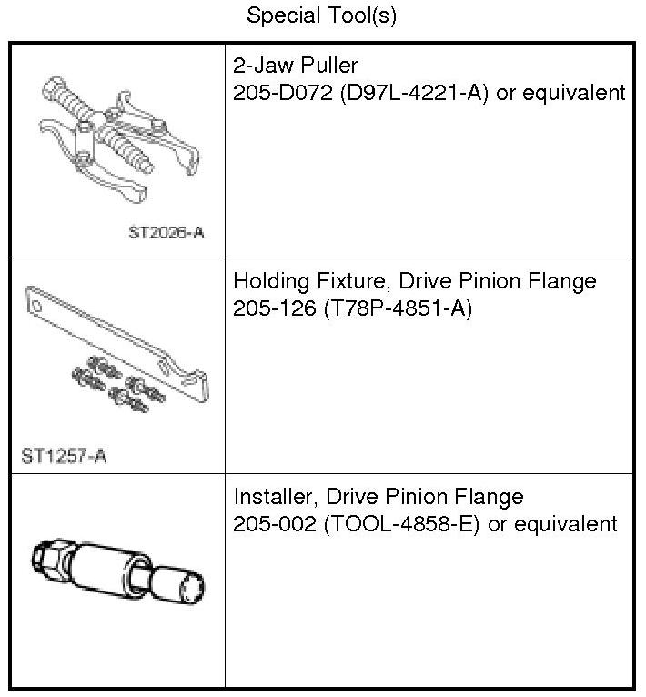
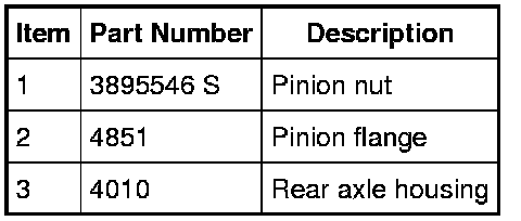
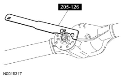
7. Using the Drive Pinion Flange Holding Fixture, hold the pinion flange and remove and discard the nut.
8. Index-mark the pinion flange and the drive pinion stem for correct alignment during installation.
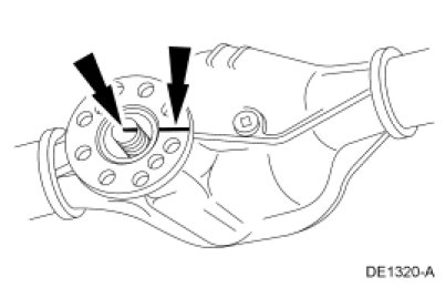
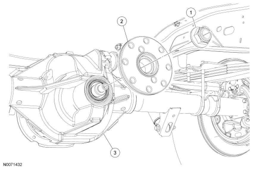
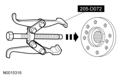
9. Using the 2-Jaw Puller, remove the pinion flange.
Installation
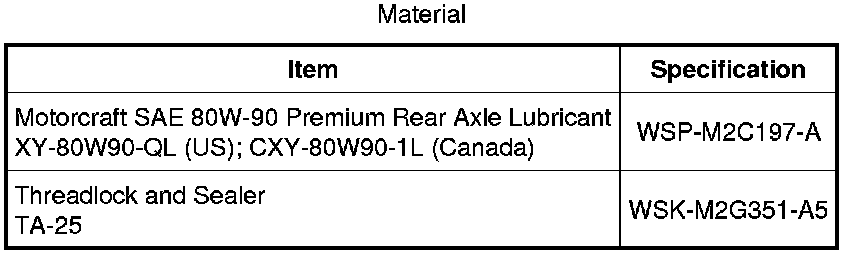
1. Lubricate the pinion flange splines with rear axle lubricant.
2. NOTE: Disregard the scribe marks if a new pinion flange is being installed.
Align the pinion flange with the drive pinion shaft.
3. NOTE: Disregard the scribe marks if a new pinion flange is being installed.
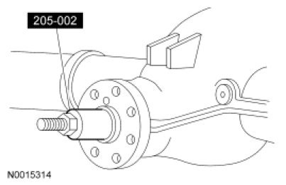
Using the Drive Pinion Flange Installer, install the pinion flange.
4. NOTICE: Use the same color new drive pinion nut for installation. If a new collapsible spacer must be installed for pinion bearing preload reduction, install the nut supplied with the new spacer or damage to the component may occur.
Position the new pinion flange nut.
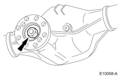
5. NOTICE: Do not, under any circumstance, loosen the nut to reduce preload. If it is necessary to reduce preload, install a new collapsible spacer and nut kit or damage to the component may occur.
NOTE: Remove the Drive Pinion Flange Holding Fixture while taking preload readings with the Nm (lb-in) torque wrench.
Using the Drive Pinion Flange Holding Fixture to hold the pinion flange, tighten the nut.
- Rotate the pinion occasionally to make sure the differential pinion bearings seat correctly. Take frequent differential pinion bearing preload readings by rotating the pinion with a Nm (lb-in) torque wrench.
- If the preload recorded prior to disassembly is lower than the specification, tighten the nut to specification. If the preload recorded prior to disassembly is higher than the specification, tighten the nut to the original reading as recorded.
- Refer to torque specifications in the Specifications.
6. NOTE: Align the index marks.
NOTE: If new bolts to retain the driveshaft to the axle are not available, coat the threads of the original bolts with threadlock.
NOTE: The driveshaft flange fits tightly on the rear axle pinion flange pilot. To make sure that the driveshaft flange seats squarely on the pinion flange, tighten the bolts evenly in a cross pattern.
Position the driveshaft flange on the pinion flange with the index marks aligned, and install the bolts.
- Tighten to 112 Nm (83 lb-ft).
7. Install the brake drums.
8. Install the rear wheel and tire.