Supplemental Restraint System (SRS) Deactivation and Reactivation
Supplemental Restraint System (SRS) Deactivation and Reactivation
Deactivation Procedure
WARNING: Always wear eye protection when servicing a vehicle. Failure to follow this instruction may result in serious personal injury.
WARNING: Always carry or place a live air bag module with the air bag and deployment door/trim cover/tear seam pointed away from the body. Do not set a live air bag module down with the deployment door/trim cover/tear seam face down. Failure to follow these instructions may result in serious personal injury in the event of an accidental deployment.
WARNING: Never probe the electrical connectors on air bag, Safety Canopy(R) or side air curtain modules. Failure to follow this instruction may result in the accidental deployment of these modules, which increases the risk of serious personal injury or death.
NOTE: The air bag warning indicator illuminates when the correct Restraints Control Module (RCM) fuse is removed and the ignition is ON.
NOTE: The Supplemental Restraint System (SRS) must be fully operational and free of faults before releasing the vehicle to the customer.
1. Turn all vehicle accessories OFF.
2. Turn the ignition OFF.
3. At the Smart Junction Box (SJB), located below the RH side of the instrument panel, remove the RCM fuse 8 (10A) from the SJB. For additional information, refer to the Wiring Diagram.
4. Turn the ignition ON and visually monitor the air bag warning indicator for at least 30 seconds. The air bag warning indicator will remain lit continuously (no flashing) if the correct RCM fuse has been removed. If the air bag warning indicator does not remain lit continuously, remove the correct RCM fuse before proceeding.
5. Turn the ignition OFF.
6. WARNING: Always deplete the backup power supply before repairing or installing any new front or side air bag supplemental restraint system (SRS) component and before servicing, removing, installing, adjusting or striking components near the front or side impact sensors or the restraints control module (RCM). Nearby components include doors, instrument panel, console, door latches, strikers, seats and hood latches.
Refer to the Description and Operation portion of Air Bag Systems for location of the RCM and impact sensor(s).
To deplete the backup power supply energy, disconnect the battery ground cable and wait at least 1 minute. Be sure to disconnect auxiliary batteries and power supplies (if equipped).
Failure to follow these instructions may result in serious personal injury or death in the event of an accidental deployment.
Disconnect the battery ground cable and wait at least 1 minute.
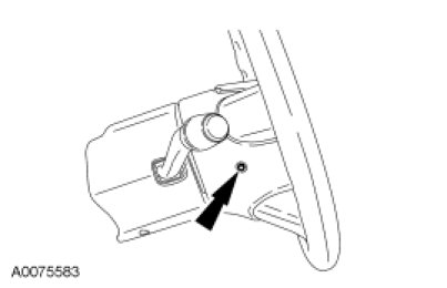
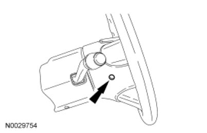
7. Remove the 2 driver air bag module bolts (1 shown).
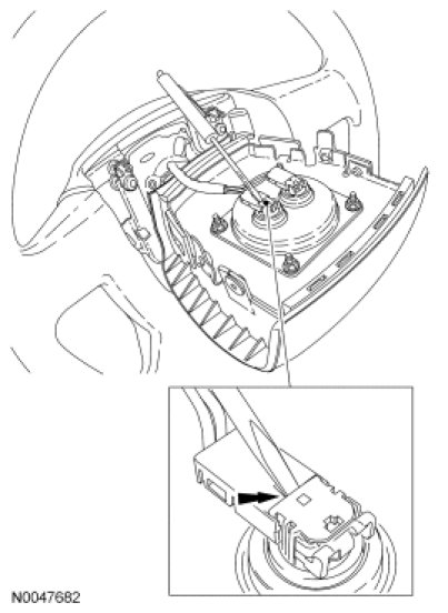
8. NOTICE: Do not pull the driver air bag module electrical connectors out by the locking buttons. Damage to the locking buttons may occur.
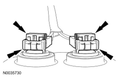
Using a small screwdriver as shown, lift up and release the locking buttons on the driver air bag module electrical connectors. With the locking buttons released, remove the electrical connectors and the driver air bag module.
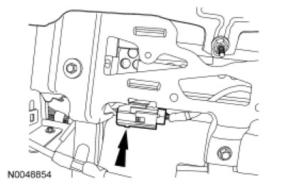
9. Open the glove compartment door fully to access the passenger air bag electrical connector.
10. Release the tab and disconnect the passenger air bag module electrical connector.
11. Install the RCM fuse 8 (10A) to the SJB.
12. Connect the battery ground cable.
Reactivation Procedure
1. Remove the RCM fuse 8 (10A) from the SJB.
2. Disconnect the battery ground cable and wait at least one minute.
3. Connect the passenger air bag module electrical connector.
4. Close the glove compartment door.
5. NOTICE: Do not install the driver air bag module electrical connectors by the locking buttons. Damage to the locking buttons may occur.
NOTICE: The driver air bag module electrical connector locking buttons must be in the released position when the connector is being installed or connector damage may occur.
With the locking buttons released, install the driver air bag module electrical connectors fully into the driver air bag module and seat the locking buttons.
6. Install the 2 driver air bag module bolts (1 shown).
- Tighten to 6 Nm (53 lb-in).
7. Make sure all restraint system diagnostic tool(s) that may have been installed during the repair have been removed from the vehicle and all SRS components are connected.
8. Turn the ignition from OFF to ON.
9. Install RCM fuse 8 (10A) to the SJB.
10. WARNING: Make sure no one is in the vehicle and there is nothing blocking or placed in front of any air bag module when the battery is connected. Failure to follow these instructions may result in serious personal injury in the event of an accidental deployment.
Connect the battery ground cable.
11. Prove out the SRS as follows:
Turn the ignition from ON to OFF. Wait 10 seconds, then turn the ignition back to ON and visually monitor the air bag warning indicator with the air bag modules installed. The air bag warning indicator will light continuously for approximately 6 seconds and then turn off. If an air bag SRS fault is present, the air bag warning indicator will:
- fail to light.
- remain lit continuously.
- flash at a 5Hz rate (RCM not configured).
The air bag warning indicator may not illuminate until approximately 30 seconds after the ignition has been turned from the OFF to the ON position. This is the time required for the RCM to complete the testing of the SRS. If the air bag warning indicator is inoperative and an SRS fault exists, a chime will sound in a pattern of 5 sets of 5 beeps. If this occurs, the air bag warning indicator and any SRS fault discovered must be diagnosed and repaired.
Clear all continuous RCM and Occupant Classification System Module (OCSM) DTCs using a scan tool.