Removal and Installation
- With the vehicle in NEUTRAL, position it on a hoist. For additional information, refer to
JACKING & LIFTING
.
- Remove the Evaporative Emission (EVAP) canister purge valve. For additional information, refer to
EVAPORATIVE EMISSIONS
.
- Recover the refrigerant. For additional information, refer to
CLIMATE CONTROL SYSTEM - GENERAL INFORMATION AND DIAGNOSTICS
.
- Remove the 4 cross vehicle beam nuts and remove the beam.
- Detach the wire harness retainer.
- To install, tighten to 30 Nm (22 lb-ft).
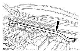 Courtesy of FORD MOTOR CO.
- Remove the evaporator outlet line fitting nut and disconnect the fitting.
- Discard the O-ring seal and gasket seal.
- To install, tighten to 15 Nm (133 lb-in).
- Remove the evaporator inlet line fitting bracket bolt.
- To install, tighten to 15 Nm (133 lb-in).
- Remove the evaporator inlet line fitting nut and disconnect the fitting.
- Discard the O-ring seal and gasket seal.
- To install, tighten to 15 Nm (133 lb-in).
- Remove the Thermostatic Expansion Valve (TXV) manifold and tube bracket bolt.
- To install, tighten to 9 Nm (80 lb-in).
- Remove the auxiliary evaporator outlet line fitting nut and disconnect the fitting.
- Discard the O-ring seal.
- To install, tighten to 15 Nm (133 lb-in).
- Remove the auxiliary evaporator inlet line fitting nut and disconnect the fitting.
- Discard the O-ring seal.
- To install, tighten to 15 Nm (133 lb-in).
- Remove the TXV
fitting nut and disconnect the fitting.
- Discard the O-ring seals.
- To install, tighten to 8 Nm (71 lb-in).
- Remove the TXV
manifold and tube assembly.
- To install, reverse the removal procedure.
- Evacuate, leak test and charge the refrigerant system. For additional information, refer to
CLIMATE CONTROL SYSTEM - GENERAL INFORMATION AND DIAGNOSTICS
.