CAUTION:
If installing a new cushion foam pad, the heater mat cannot be reused. A new heater mat must be installed. Failure to follow this instruction may result in component or system failure.
NOTE:
A new heater mat can be attached to the foam pad where the old heater mat was removed but a used heater mat should not be reattached to any foam pad.
- Seats receiving a new OCS system service kit, install the new cushion heater mat onto the new cushion foam pad.
All seats
- Position the cushion trim cover to the cushion foam pad and install the hog rings.
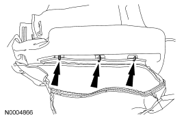 Courtesy of FORD MOTOR CO.
- Install the seat wire harness.
Seats with manual recline
- Position the manual recliner and drive the 2 large roll pins into the cushion frame and through the front manual recliner eyelets.
Seats with power recline
- Position the power recliner to the cushion frame and install the 3 bolts.
- Tighten to 10 Nm (89 lb-in).
- Drive the 2 large roll pins into the cushion frame and through the front power recliner eyelets.
- Connect the power recliner electrical connector.
Heated seats
- Slide the heated seat module onto the bracket, making sure it is locked in place and install the rivet. Connect the heated seat module electrical connector.
Seats with an OCS system service kit
WARNING:
Make sure the front passenger seat repair is complete, the seat and all attached components (head restraint, seat side shield, etc.) are correctly assembled, and the seat is correctly installed to the vehicle before carrying out the System Reset. Failure to follow these instructions may result in incorrect operation of the occupant classification sensor (OCS) system and increases the risk of serious personal injury or death in a crash.
CAUTION:
Inspect the occupant classification sensor (OCS) assembly, seat cushion frame and support assembly for any foreign objects before installing the OCS assembly to the seat cushion frame. If any foreign objects are found, remove them. Failure to follow these instructions may result in incorrect OCS system operation or failure.
CAUTION:
Failure to route the occupant classificatino sensor (OCS) system components through the correct seat cushion support opening may cause component failure.
NOTE:
If the original equipment (OE) occupant classification sensor (OCS) system is not being installed, install an OCS system service kit using all parts in the kit.
- Position the OCS system to the seat cushion frame.
- Using an OCS system service kit, feed the OCSM, electrical connector, wire harness, pressure sensor and hose through the largest opening at the front of the seat cushion frame support assembly.
- Position the seat cushion pad and bladder to the seat cushion frame.
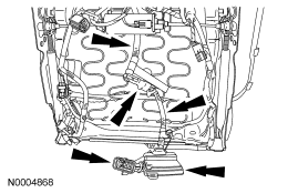 Courtesy of FORD MOTOR CO.
- Install the OCSM.
- Position the OCSM and install the rivets.
- Connect the electrical connector.
- The OCSM must be correctly positioned and securely riveted in place. Failure to do so may set a DTC in the RCM.
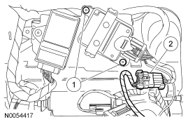 Courtesy of FORD MOTOR CO.
Power seats with an OCS system service kit
- Tie strap the unused OCS system pressure sensor electrical connector to the seat wiring harness.
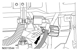 Courtesy of FORD MOTOR CO.
Seats with an OE OCS
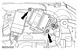
- Install the OCSM and rivets to the cushion frame bracket.
- The OCSM must be correctly positioned and securely riveted in place. Failure to do so may set a DTC in the RCM.
 Courtesy of FORD MOTOR CO.
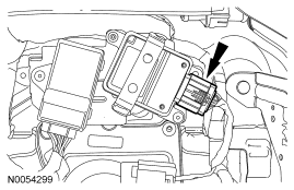
- Connect the OCSM electrical connector.
 Courtesy of FORD MOTOR CO.
WARNING:
Make sure the front passenger seat repair is complete, the seat and all attached components (head restraint, seat side shield, etc.) are correctly assembled, and the seat is correctly installed to the vehicle before carrying out the System Reset. Failure to follow these instructions may result in incorrect operation of the occupant classification sensor (OCS) system and increases the risk of serious personal injury or death in a crash.
CAUTION:
Inspect the occupant classification sensor (OCS) assembly, seat cushion frame and support assembly for any foreign objects before installing the OCS assembly to the seat cushion frame. If any foreign objects are found, remove them. Failure to follow these instructions may result in incorrect OCS system operation or failure.
CAUTION:
Failure to route the occupant classification sensor (OCS) system components through the correct seat cushion support opening may cause component failure.
CAUTION:
While positioning the seat cushion frame and occupant classification sensor (OCS) assembly, be careful not to damage any of the components. Failure to do so may result in component failure.
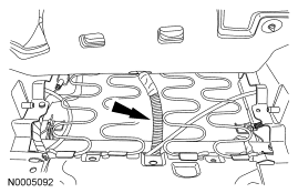
- Position the OCS bladder to the cushion frame.
- Feed the pressure sensor and hose through the center opening in the cushion frame wires.
 Courtesy of FORD MOTOR CO.
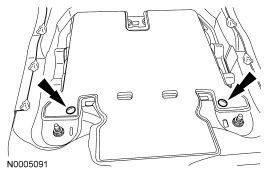
- Install the OCS bladder pin-type retainers.
 Courtesy of FORD MOTOR CO.
All seats
NOTE:
Make sure the pressure sensor is correctly installed and retained to the seat track bracket and the pressure sensor hose is not kinked during installation.
- Install the seat track. For additional information, refer to Seat Track - Front .
- Install the front seat backrest. For additional information, refer to Seat Backrest - Front .
- Install the seat. For additional information, refer to Seat - Front .
- Repower the SRS. Do not prove out the SRS at this time.
For additional information, refer to Supplemental Restraint System (SRS) Depowering and Repowering in the General Procedures portion of SUPPLEMENTAL RESTRAINT SYSTEM
article.
WARNING:
Make sure the front passenger seat repair is complete, the seat and all attached components (head restraint, seat side shield, etc.) are correctly assembled, and the seat is correctly installed to the vehicle before carrying out the System Reset. Failure to follow these instructions may result in incorrect operation of the occupant classification sensor (OCS) system and increases the risk of serious personal injury or death in a crash.
WARNING:
Install a new occupant classification sensor (OCS) system service kit as a complete assembly. Never install only part of the kit components. Failure to follow this instruction may result in incorrect operation of the OCS system and increases the risk of serious personal injury or death in a crash.
CAUTION:
To prevent system failure, it is necessary to carry out the occupant classification sensor (OCS) system reset when a front passenger seat cushion is disassembled, a new trim cover installed or an OCS system service kit is installed. A scan tool is used to carry out the OCS system reset command.
CAUTION:
To prevent system failure the following precautions must be taken before carrying out the occupant classification sensor (OCS) system reset:
- Make sure the voltage to the occupant classification system module (OCSM) is above 8.0 volts and less than 18.0 volts.
- Make sure the OCS system is not at a temperature below 6°C (42°F) or above 36°C (97°F) when initiating the OCS system reset process. If the vehicle has been exposed to extreme cold or hot temperatures, the vehicle must be exposed and kept at a temperature within the limits, 6°C to 36°C (42°F to 97°F) for a minimum of 30 minutes.
- Make sure nothing is present on the passenger seat before carrying out the OCS system reset and nothing is placed on the seat during the process.
- Make sure a minimum 8-second time period has passed after cycling the ignition switch ON before the carrying out the OCS system reset process.
NOTE:
If the first attempt to carry out the OCS system reset is unsuccessful, a second attempt must be made. If the second attempt to carry out the OCS system reset is unsuccessful, a new OCS system service kit must be installed.
- Carry out the OCS system reset.
NOTE:
The ignition switch must be cycled after the OCS system reset.
- Cycle the ignition switch from ON to OFF.
- Prove out the SRS as follows:
Turn the ignition key from ON to OFF. Wait 10 seconds, then turn the key back to ON and visually monitor the air bag warning indicator with the air bag modules installed. The air bag warning indicator will light continuously for approximately 6 seconds and then turn off. If an air bag SRS fault is present, the air bag warning indicator will:
- fail to light.
- remain lit continuously.
- flash.
The flashing might not occur until approximately 30 seconds after the ignition switch has been turned from the OFF to the ON position. This is the time required for the RCM to complete the testing of the SRS. If the air bag warning indicator is inoperative and a SRS fault exists, a chime will sound in a pattern of 5 sets of 5 beeps. If this occurs, the air bag warning indicator and any SRS fault discovered must be diagnosed and repaired.
Clear all continuous DTCs from the RCM and OCSM using a scan tool.
NOTE:
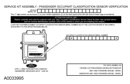
When installing a new OCS system service kit, a prepaid return postcard is provided with the new OCS. The serial number for the new part and the vehicle identification number (VIN) must be recorded and sent to Ford Motor Company.
- If a new OCS system service kit was installed, fill out the necessary information on the OCS traceability card and return it along with the complete inoperative OCS system to Ford Motor Company.
- When returning the inoperative OCS, include: seat cushion foam pad, bladder, OCSM, pressure sensor (transducer), hose, electrical connectors and wire harness (service part OCS only).
 Courtesy of FORD MOTOR CO.