Pinpoint Test C: DTC B1046, B1047, B1048, B1049, B1054, B1055, B1056, B1057, B1058, B1059, B2A3F And/Or B2A40
Air Bag and Safety Belt Pretensioner Supplemental Restraint System (SRS)
Pinpoint Tests
Pinpoint Test C: DTC B1046, B1047, B1048, B1049, B1054, B1055, B1056, B1057, B1058, B1059, B2A3F and/or B2A40
Refer to Wiring Diagram Set 46, Supplemental Restraint System for schematic and connector information. Diagrams By Number
Normal Operation
The Restraints Control Module (RCM) monitors all deployable circuits for a cross link fault between circuits. If a fault is detected, a DTC will be stored in memory for each of the deployable circuits. The RCM sends a message to the Instrument Cluster (IC) module to flash a Lamp Fault Code (LFC) on the air bag warning indicator. When a normal circuit fault is detected (one loop is either shorted to battery/ground, has an open circuit or has low resistance), crosslink diagnostics will not be active. Once the normal fault is repaired, crosslink diagnostics will resume.
B2A3F-B1059:
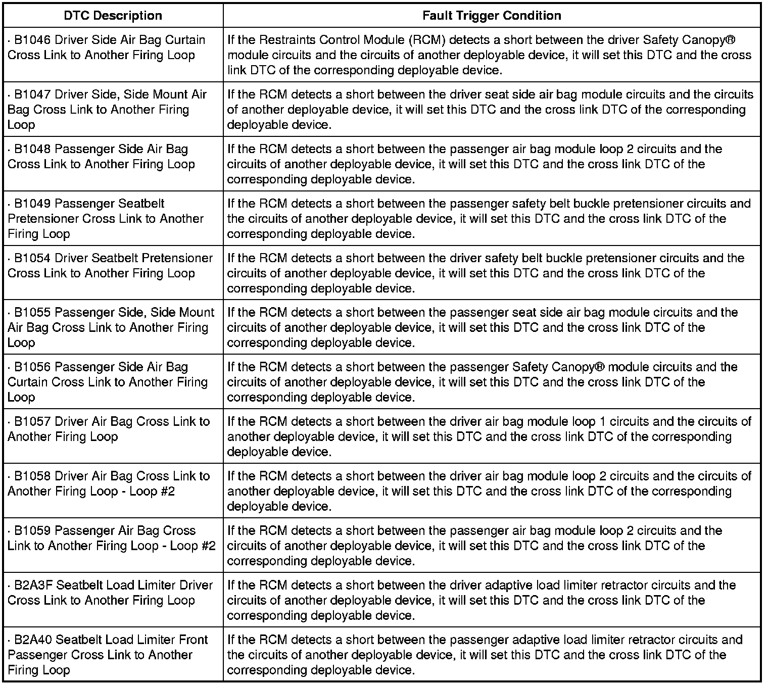
This pinpoint test is intended to diagnose the following:
- Wiring, terminals or connectors
- RCM
PINPOINT TEST C: DTC B1046, B1047, B1048, B1049, B1054, B1055, B1056, B1057, B1058, B1059, B2A3F and/or B2A40
WARNING: Do not handle, move or change the original horizontal mounting position of the restraints control module (RCM) while the RCM is connected and the ignition switch is ON. Failure to follow this instruction may result in the accidental deployment of the Safety Canopy(R) and cause serious personal injury or death.
WARNING: Never probe the electrical connectors on air bag, Safety Canopy(R) or side air curtain modules. Failure to follow this instruction may result in the accidental deployment of these modules, which increases the risk of serious personal injury or death.
WARNING: Never probe the electrical connectors on safety belt buckle/retractor pretensioners or adaptive load limiting retractors. Failure to follow this instruction may result in the accidental deployment of the safety belt pretensioners or adaptive load limiting retractors, which increases the risk of serious personal injury or death.
NOTICE: Use the correct probe adapter(s) from the Flex Probe Kit when making measurements. Failure to use the correct probe adapter(s) may damage the connector.
Most faults are due to connector and/or wiring concerns. Carry out a thorough inspection and verification before proceeding with the pinpoint test. Inspection and Verification
NOTE: The Supplemental Restraint System (SRS) must be fully operational and free of faults before releasing the vehicle to the customer.
NOTE: SRS components should only be disconnected or reconnected when instructed to do so within a pinpoint test step. Failure to follow this instruction may result in incorrect diagnosis of the SRS.
NOTE: Cross link DTCs will be retrieved in pairs, the highest priority along with the DTC of the cross linked component.
-------------------------------------------------
C1 RETRIEVE RCM DTCs
- Enter the following diagnostic mode on the scan tool: Self Test - RCM .
- Were any cross link DTCs retrieved on-demand during the self test?
Yes
This fault cannot be cleared until it is corrected and the DTC is no longer retrieved on-demand during self test. GO to C2.
No
This is an intermittent fault when present as a CMDTC only. GO to C4.
-------------------------------------------------
C2 CHECK DEPLOYABLE CIRCUITS FOR A CROSS LINK FAULT
- Ignition OFF.
- Depower the SRS. Refer to Supplemental Restraint System (SRS) Depowering and Repowering Supplemental Restraint System (SRS) Depowering and Repowering.
- Disconnect: RCM C310a and C310b.
- NOTE: To gain access to the Safety Canopy(R) connector, the D-pillar trim panel must be removed and the rear of the headliner slightly lowered. Refer to Headliner.
- Disconnect ALL of the affected deployable devices.
- Using the following table, measure the resistance between the circuits of the affected deployable devices.
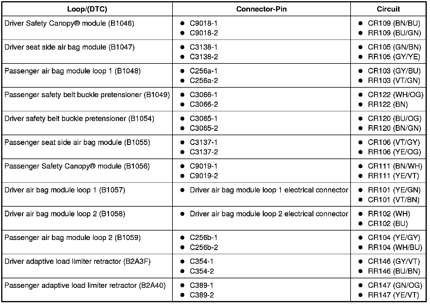
- Are the resistances greater than 10,000 ohms between the affected circuits?
Yes
GO to C3.
No
REPAIR the affected circuits. GO to C5.
-------------------------------------------------
C3 CONFIRM THE RCM FAULT
NOTE: Make sure all restraint system components, sensor electrical connectors and the RCM electrical connectors are connected before carrying out the self test. If not, DTCs will be recorded.
- Connect: All Previously Disconnected Restraint System Component(s).
- Connect: RCM C310a and C310b.
- Repower the SRS. Do not prove out the SRS at this time. Refer to Supplemental Restraint System (SRS) Depowering and Repowering Supplemental Restraint System (SRS) Depowering and Repowering.
- Enter the following diagnostic mode on the scan tool: Self Test - RCM.
- Were any cross link DTCs retrieved on-demand during self-test?
Yes
INSTALL a new RCM and CARRY OUT Programmable Module Installation (PMI) Programming and Relearning. REFER to Restraints Control Module (RCM) Service and Repair. GO to C5.
No
In the process of diagnosing the fault, the fault condition has become intermittent. Do not install any new SRS components at this time. SRS components should only be installed when directed to do so in the pinpoint test. GO to C4.
-------------------------------------------------
C4 CHECK FOR AN INTERMITTENT FAULT
- Ignition OFF.
- Depower the SRS. Refer to Supplemental Restraint System (SRS) Depowering and Repowering Supplemental Restraint System (SRS) Depowering and Repowering.
- Disconnect ALL of the affected deployable devices.
- Inspect the wiring harness(es) for any type of damage. Repair as necessary. Refer to Wiring Diagram Set 46, Supplemental Restraint System for schematic and connector information. Diagrams By Number
- Repower the SRS. Do not prove out the SRS at this time. Refer to Supplemental Restraint System (SRS) Depowering and Repowering Supplemental Restraint System (SRS) Depowering and Repowering.
- Enter the following diagnostic mode on the scan tool: Self Test - RCM.
- Were any cross link DTCs retrieved on-demand during self-test?
Yes
The fault condition is now present. This fault cannot be cleared until it is corrected and the DTC is no longer retrieved on-demand during self test. GO to C2.
No
CHECK for causes of the intermittent fault. ATTEMPT to recreate the hard fault by flexing the wire harness and cycling the ignition frequently. Do not install any new SRS components at this time. SRS components should only be installed when directed to do so in the pinpoint test. REPAIR any intermittent wiring, terminal or connector concerns found. GO to C5.
-------------------------------------------------
C5 CHECK FOR ADDITIONAL SRS DTCs
- Ignition OFF.
- WARNING: Turn the ignition OFF and wait one minute to deplete the backup power supply. Failure to follow this instruction may result in serious personal injury or death in the event of an accidental deployment.
- Reconnect all SRS components (if previously disconnected).
- If previously directed to depower the SRS, repower the SRS. Do notprove out the SRS at this time. Refer to Supplemental Restraint System (SRS) Depowering and Repowering Supplemental Restraint System (SRS) Depowering and Repowering.
- Ignition ON.
- Enter the following diagnostic mode on the scan tool: Self Test - Restraints.
- NOTE: When selecting Restraints from the Self Test menu, DTCs will be retrieved from the RCM and OCSM.
- Are any RCM and/or OCSM DTCs retrieved indicating a fault?
Yes
Do not clear any DTCs until all DTCs have been resolved. GO to the DTC Charts for pinpoint test direction. [1][2]Diagnostic Trouble Code Descriptions
No
CLEAR all RCM and OCSM CMDTCs. PROVE OUT the SRS. Repair is complete. RETURN the vehicle to the customer.
-------------------------------------------------