Pinpoint Test I: DTCs C1279, C1280, C1281, C1282, C1516, C1517, C1963, C1975, C2769, C2770 And U0074
Anti-Lock Control
Pinpoint Tests
Pinpoint Test I: DTCs C1279, C1280, C1281, C1282, C1516, C1517, C1963, C1975, C2769, C2770 and U0074
Refer to Wiring Diagram Set 42, Vehicle Dynamic Systems for schematic and connector information. Diagrams By Number
Normal Operation
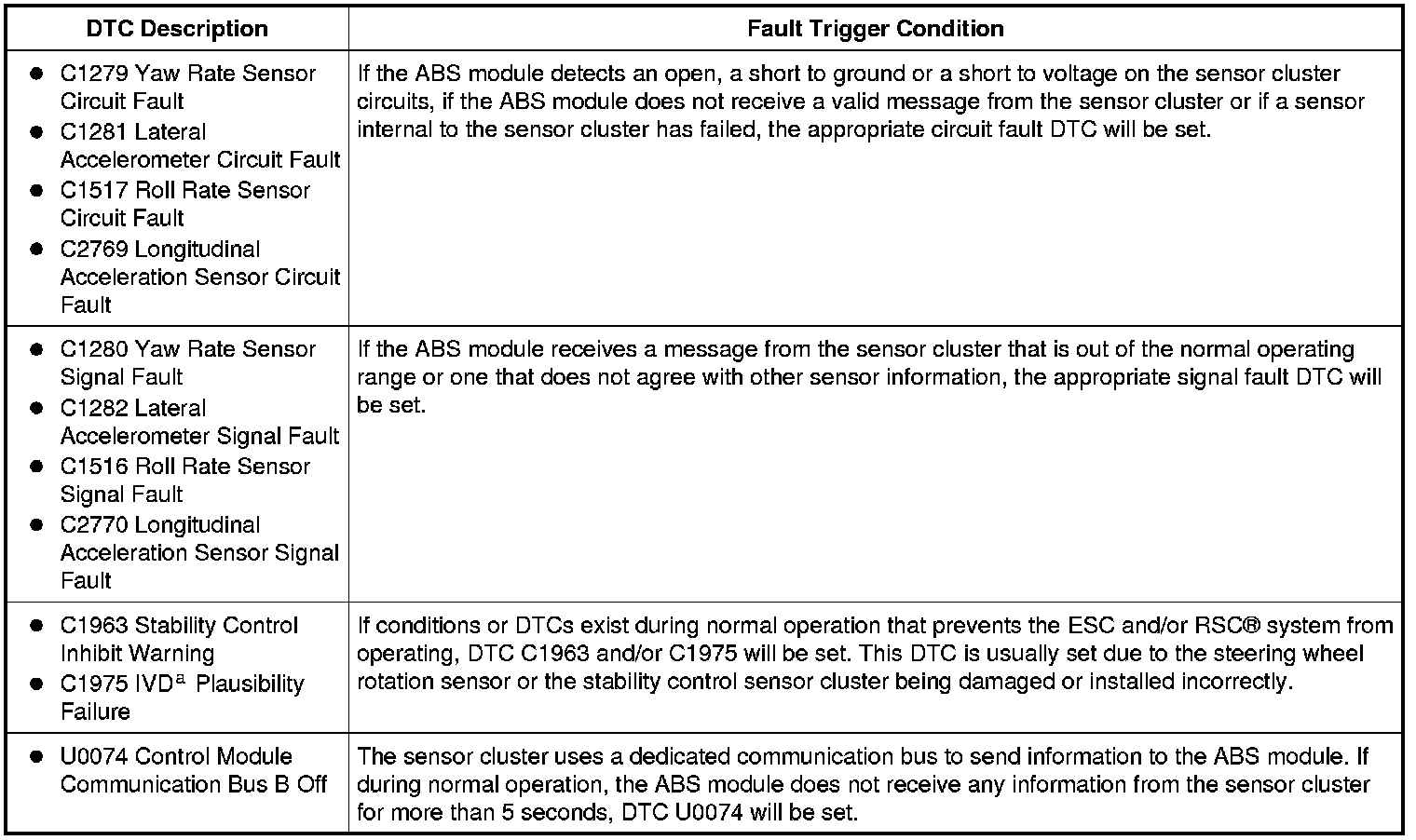
The sensor cluster measures the yaw rate, roll rate and vehicle acceleration, then sends the signal through a secondary, dedicated Controller Area Network (CAN) bus to the ABS module. The ABS module uses this information for Electronic Stability Control (ESC) and Roll Stability Control (RSC(R)) system operation. The ABS module also compares this information to information it receives from other sensors (brake pedal input, steering wheel rotation sensor, etc.) to determine how valid the information is and to determine if an instability event is about to occur.
Fused ignition voltage is provided to the sensor cluster along circuit CBP34 (VT/BN) and ground is provided to the sensor along circuit GD145 (BK/BU). The sensor cluster and the ABS module communicate along circuits VCA23 (BU/WH) and VCA24 (GN/OG). An open circuit or a short to power or ground on any one of these 4 circuits will cause the ABS module to set a DTC. Also, if the sensor cluster is not mounted in the correct position, with the electrical connector facing the rear of the vehicle, the ABS module will also set DTCs.
C1279-C2770 / U0074:
a Interactive Vehicle Dynamics
This pinpoint test is intended to diagnose the following:
- Wiring, terminals or connectors
- Stability control sensor cluster
- ABS module
PINPOINT TEST I: DTCs C1279, C1280, C1281, C1282, C1516, C1517, C1963, C1975, C2769, C2770 AND U0074
NOTICE: Use the Flex Probe Kit for all test connections to prevent damage to the wiring terminals. Do not use standard multi-meter probes.
NOTE: The vehicle must be on level ground, not on a hoist and at a complete standstill. Any vehicle movement will result in false values for this test.
-------------------------------------------------
I1 CHECK FOR RETURNING DTCs
- Connect the scan tool.
- Ignition ON.
- Using the scan tool, clear all ABS module DTCs.
- Test drive the vehicle above 20 km/h (12 mph), making several tight circles and hard braking maneuvers.
- Retrieve and record any ABS module DTCs.
- Does C1279, C1280, C1281, C1282, C1516, C1517, C1963, C1975, C2769 and/or C2770 return?
Yes
If DTC C1963 and/or C1975 are retrieved, GO to I2.
If DTC C1279, C1280, C1281, C1282, C1516, C1517, C2769 or C2770 is retrieved, GO to I3.
If DTC U0074 is retrieved, GO to I7.
If any other DTCs are retrieved, GO to the ABS Module DTC Chart. ABS Module DTC Chart
No
The system is operating correctly at this time. CLEAR the DTCs. REPEAT the self-test.
-------------------------------------------------
I2 CHECK THE STABILITY CONTROL SENSOR CLUSTER CONDITION AND INSTALLATION
- Inspect the stability control sensor cluster for cracks in the case, broken anchor tabs, broken electrical connector and correct installation. Refer to Stability Control Sensor Cluster Service and Repair.
- Is the sensor cluster installed correctly and undamaged?
Yes
GO to I3.
No
REINSTALL or INSTALL new as necessary. CLEAR the DTCs. CYCLE the ignition key. REPEAT the self test.
-------------------------------------------------
I3 CHECK THE VOLTAGE TO THE SENSOR CLUSTER
- Ignition OFF.
- Disconnect: Sensor Cluster C3073.
- Ignition ON.
- Measure the voltage between sensor cluster C3073-4, circuit CBP34 (VT/BN), harness side and ground.
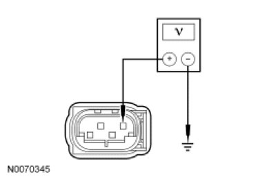
- Is the voltage greater than 10 volts?
Yes
GO to I4.
No
VERIFY that BJB fuse 34 (10A) is OK. If OK, REPAIR circuit CBP34 (VT/BN). CLEAR the DTCs. CYCLE the ignition key. REPEAT the self-test.
If not OK, REFER to the Wiring Diagrams to identify possible causes of the circuit short. CLEAR the DTCs. CYCLE the ignition key. REPEAT the self-test.
-------------------------------------------------
I4 CHECK CIRCUIT GD145 (BK/BU) FOR AN OPEN
- Ignition OFF.
- Measure the resistance between sensor cluster C3073-1, circuit RCA09 (GN/VT), harness side and ground.
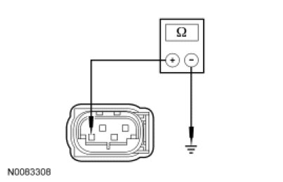
- Is the resistance less than 5 ohms?
Yes
GO to I5.
No
REPAIR circuit GD145 (BK/BU). CLEAR the DTCs. CYCLE the ignition key. REPEAT the self-test.
-------------------------------------------------
I5 CHECK THE ABS MODULE YAW RATE (YAW_RATE_2) PID
- Ignition OFF.
- Connect: Sensor Cluster C3073.
- Connect: ABS Module C135.
- Ignition ON.
- Enter the following diagnostic mode on the scan tool: DataLogger - ABS.
- NOTE: The vehicle must be on level ground and at a complete standstill. Any vehicle movement results in false values for this test.
- Monitor the YAW_RATE_2 PID.
- Is the YAW_RATE_2 PID value between -0.05 and 0.05?
Yes
GO to I6.
No
CHECK the mounting of the sensor cluster. If OK, INSTALL a new sensor cluster. REFER to Stability Control Sensor Cluster Service and Repair. CLEAR the DTCs. CYCLE the ignition key. REPEAT the self-test.
-------------------------------------------------
I6 CHECK THE ABS MODULE LATERAL ACCELERATION (LAT_ACEL_2) PID
- NOTE: The vehicle must be on level ground and at a complete standstill. Any vehicle movement results in false values for this test.
- Monitor the LAT_ACCL_2 PID.
- Is the LAT_ACCL_2 PID value between -0.007 and 0.007?
Yes
GO to I7.
No
CHECK the mounting of the sensor cluster. If OK, INSTALL a new sensor cluster. REFER to Stability Control Sensor Cluster Service and Repair. CLEAR the DTCs. CYCLE the ignition key. REPEAT the self-test.
-------------------------------------------------
I7 CHECK CIRCUITS VCA23 (BU/WH) AND VCA24 (GN/OG) FOR AN OPEN
- Ignition OFF.
- Disconnect: ABS Module C135.
- Disconnect: Sensor Cluster C3073.
- Measure the resistance between ABS module C135, harness and sensor cluster C3073, harness side using the following chart:
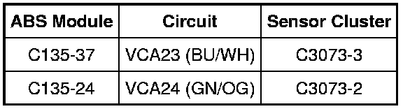
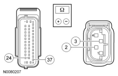
- Are the resistances less than 5 ohms?
Yes
GO to I8.
No
REPAIR the affected circuit(s). CLEAR the DTCs. CYCLE the ignition key. REPEAT the self-test.
-------------------------------------------------
I8 CHECK CIRCUITS VCA23 (BU/WH) AND VCA24 (GN/OG) FOR A SHORT TO GROUND
- Measure the resistance between ground and:
- sensor cluster C3073-3, circuit VCA23 (BU/WH), harness side.
- sensor cluster C3073-2, circuit VCA24 (GN/OG), harness side.
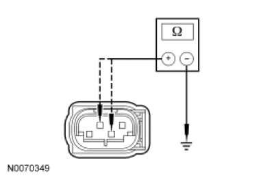
- Are the resistances greater than 10,000 ohms?
Yes
GO to I9.
No
REPAIR the affected circuit(s). CLEAR the DTCs. CYCLE the ignition key. REPEAT the self-test.
-------------------------------------------------
I9 CHECK CIRCUITS VCA23 (BU/WH) AND VCA24 (GN/OG) FOR A SHORT TO VOLTAGE
- Ignition ON.
- Measure the voltage between ground and:
- sensor cluster C3073-3, circuit VCA23 (BU/WH), harness side.
- sensor cluster C3073-2, circuit VCA24 (GN/OG), harness side.
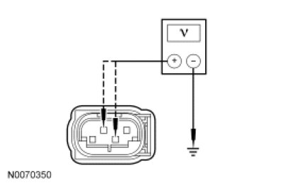
- Is any voltage present?
Yes
REPAIR the affected circuit(s). CLEAR the DTCs. CYCLE the ignition key. REPEAT the self-test.
No
GO to I10.
-------------------------------------------------
I10 CHECK FOR CORRECT ABS MODULE OPERATION
- Disconnect all the ABS connectors.
- Check for:
- corrosion.
- pushed-out pins.
- spread terminals.
- Connect all the ABS connectors and make sure they seat correctly.
- Operate the system and verify the concern is still present.
- Is the concern still present?
Yes
INSTALL a new ABS module. REFER to Anti-Lock Brake System (ABS) Module Service and Repair. CLEAR the DTCs. CYCLE the ignition key. REPEAT the self-test.
No
The system is operating correctly at this time. The concern may have been caused by a loose or corroded connector. CLEAR the DTCs. CYCLE the ignition key. REPEAT the self-test.
-------------------------------------------------