Pinpoint Test L: DTCs C1194, C1198, C1210, C1214, C1242, C1246, C1250, C1254, C1404, C1410, C1957 And C1958
Anti-Lock Control
Pinpoint Tests
Pinpoint Test L: DTCs C1194, C1198, C1210, C1214, C1242, C1246, C1250, C1254, C1404, C1410, C1957 and C1958
Refer to Wiring Diagram Set 42, Vehicle Dynamic Systems for schematic and connector information. Diagrams By Number
Normal Operation
The ABS module utilizes battery voltage from Battery Junction Box (BJB) fuse 57 (40A) along circuit SBB57 (WH/RD) and ground along GD121 (BK/YE) to operate the inlet and outlet valve coils.
The operating voltage required to operate the valve coils is between 10 and 16 volts. If the voltage is above or below the required operating voltage, multiple valve coil circuit fault DTCs will set.
The valve coils and circuitry are internal to the ABS module and cannot be serviced separately.
C1194-C1958:
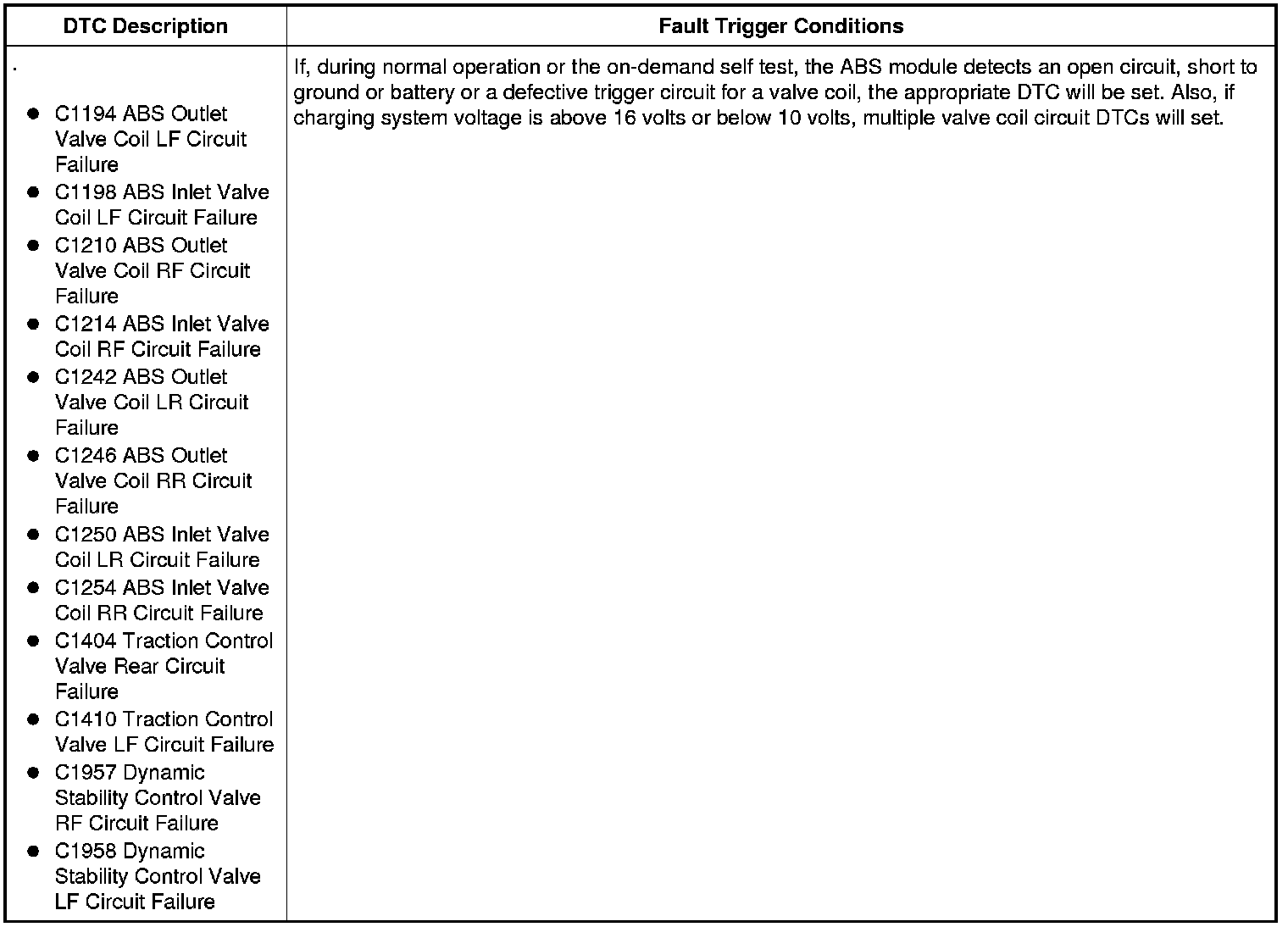
This pinpoint test is intended to diagnose the following:
- Wiring, terminals or connectors
- ABS module
PINPOINT TEST L: DTCs C1194, C1198, C1210, C1214, C1242, C1246, C1250, C1254, C1404, C1410, C1957 AND C1958
NOTICE: Use the Flex Probe Kit for all test connections to prevent damage to the wiring terminals. Do not use standard multi-meter probes.
-------------------------------------------------
L1 CHECK FOR RETURNING DTCs
- Ignition ON.
- Connect the scan tool.
- Enter the following diagnostic mode on the scan tool: Clear All CMDTCs.
- Test drive the vehicle above 32 km/h (20 mph) and carry out at least one ABS stop.
- Enter the following diagnostic mode on the scan tool: Self Test - ABS Module.
- Do any ABS module DTCs return?
Yes
REPAIR all other ABS module DTCs before repairing any valve coil failure DTCs. REFER to the ABS Module DTC Chart. ABS Module DTC Chart
If multiple (2 or more) valve coil failure DTCs return, GO to L2.
If only a single valve coil failure DTC returns, INSTALL a new ABS module. REFER to Anti-Lock Brake System (ABS) Module Service and Repair. CLEAR the DTCs. REPEAT the self-test with the brake pedal not applied.
No
The system is operating correctly at this time. INSPECT the ABS module connector for corrosion, pushed-out pins or spread terminals. TEST the system for normal operation.
-------------------------------------------------
L2 CHECK THE ABS MODULE POWER CIRCUITS FOR AN OPEN
NOTE: The battery and battery tray need to be removed to access the ABS module connector.
- Ignition OFF.
- Disconnect: BJB Fuse 15 (40A).
- Disconnect: BJB Fuse 50 (10A).
- Disconnect: BJB Fuse 57 (40A).
- Disconnect: ABS Module C135.
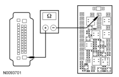
- Measure the resistance between the ABS module C135-1, circuit SBB15 (WH/RD), harness side and BJB fuse 15 (40A), output side.
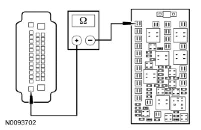
- Measure the resistance between the ABS module C135-25, circuit SBB57 (RD), harness side and BJB fuse 57 (40A), output side.
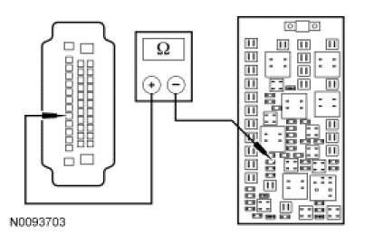
- Measure the resistance between the ABS module C135-30, circuit CBB50 (YE/OG), harness side and BJB fuse 50 (10A), output side.
- Is the resistance less than 5 ohms?
Yes
GO to L3.
No
VERIFY BJB fuse 15 (40A) is OK. If OK, REPAIR circuit SBB15 (WH/RD).
VERIFY BJB fuse 57 (40A) is OK. If OK, REPAIR circuit SBB57 (RD).
VERIFY BJB fuse 50 (10A) is OK. If OK, REPAIR circuit CBB50 (YE/OG).
CLEAR the DTCs. REPEAT the self-test.
If any fuse is not OK, REFER to the Wiring Diagrams to identify the possible causes of the circuit short.
-------------------------------------------------
L3 CHECK THE ABS MODULE GROUND CIRCUITS FOR AN OPEN
- Ignition OFF.
- Measure the resistance between ground and:
- ABS module C135-13, circuit GD121 (BK/YE), harness side.
- ABS module C135-38, circuit GD121 (BK/YE), harness side.
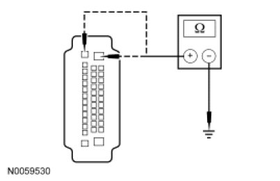
- Are the resistances less than 5 ohms?
Yes
GO to L4.
No
REPAIR the affected circuit(s). CLEAR the DTCs. REPEAT the self-test.
-------------------------------------------------
L4 CHECK FOR CORRECT ABS MODULE OPERATION
- Check ABS module C135 for:
- corrosion.
- pushed-out pins.
- spread terminals.
- Connect: ABS C135.
- Make sure the ABS connector seats correctly, then operate the system and verify the concern is still present.
- Is the concern still present?
Yes
INSTALL a new ABS module. REFER to Anti-Lock Brake System (ABS) Module Service and Repair. CLEAR the DTCs. CARRY OUT the self-test with the brake pedal not applied.
No
The system is operating correctly at this time. The concern may have been caused by a loose or corroded connector. CLEAR the DTCs. CARRY OUT the self-test with the brake pedal not applied.
-------------------------------------------------