Part 2
CamshaftRemoval (Steps 61-98)
AWD vehicles
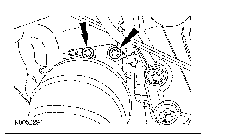
61. Remove the 2 RH halfshaft bearing support bracket bolts and the RH halfshaft/intermediate shaft assembly.
All vehicles
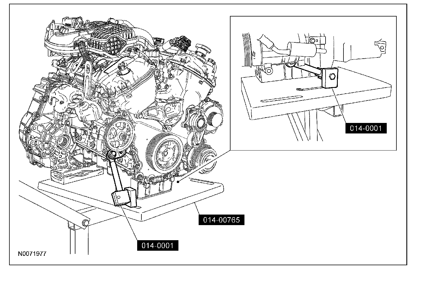
62. NOTE: Position a block of wood under the transaxle.
Install the special tools.
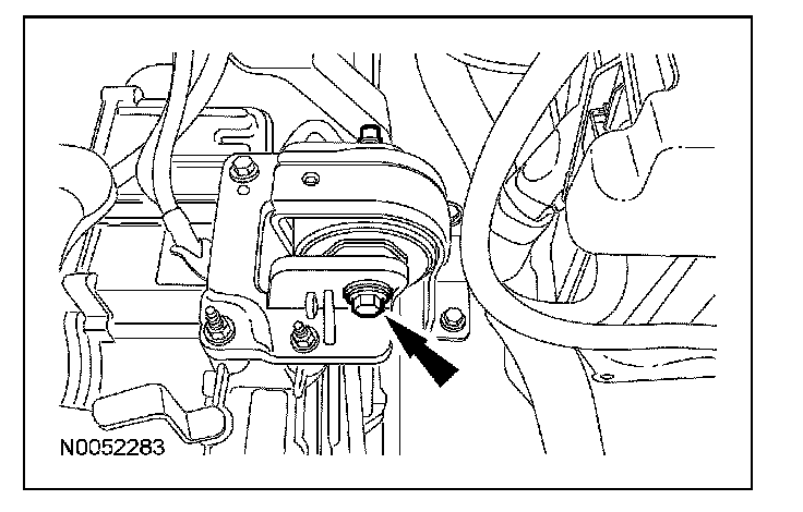
63. Remove the transaxle support insulator through bolt and nut.
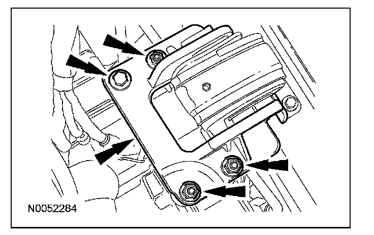
64. Remove the 3 nuts, the bolt and the transaxle support insulator bracket.
65. Remove the nut, bolt and engine mount brace.
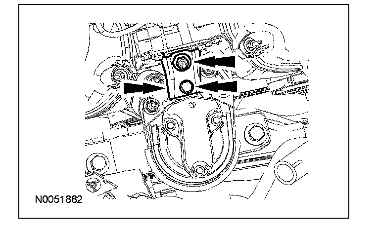
66. Remove the 4 engine mount nuts.
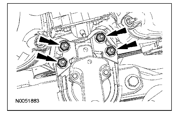
67. Remove the 3 bolts and the engine mount.
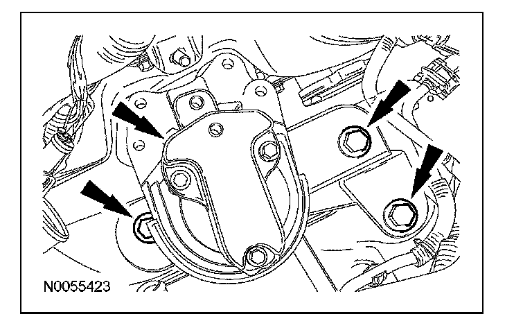
68. Lower the engine and transaxle assembly from the vehicle.
69. If equipped, detach the engine block heater wiring harness retainers and position the harness aside.
70. Disconnect the PCV hose from the PCV valve.
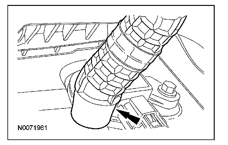
71. Disconnect the throttle body (TB) electrical connector.
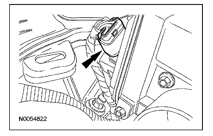
72. Detach the wiring harness retainers from the upper intake manifold.
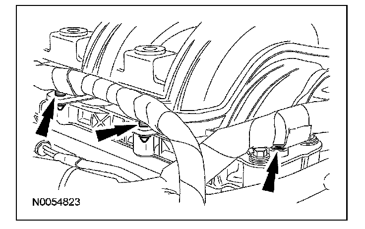
73. Remove the upper intake manifold support bracket bolt.
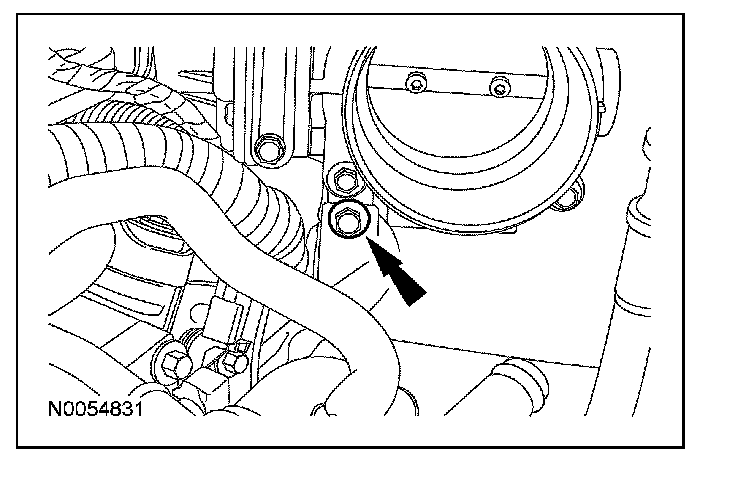
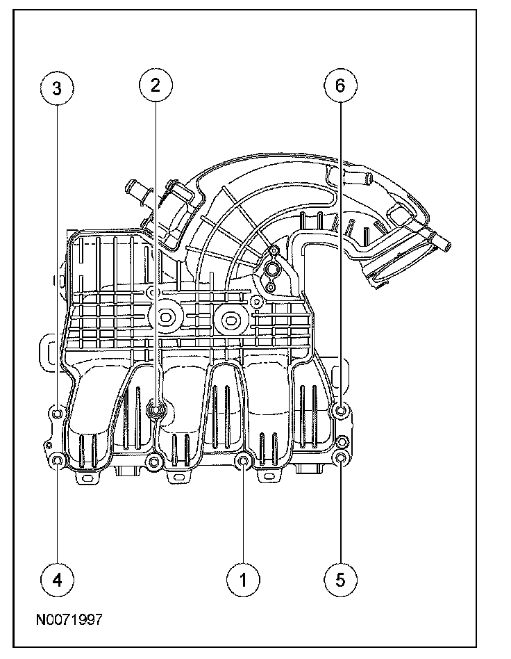
74. Remove the 6 bolts and the upper intake manifold in the following sequence.
^ Discard the gaskets.
75. Disconnect the RH catalyst monitor electrical connector.
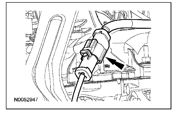
76. Disconnect the PSP switch electrical connector.
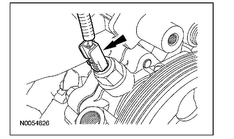
77. Disconnect the RH variable camshaft timing (VCT) solenoid electrical connector.
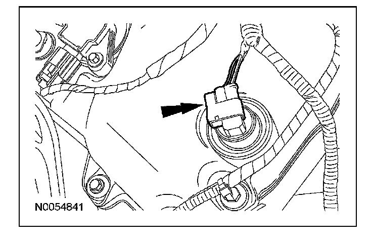
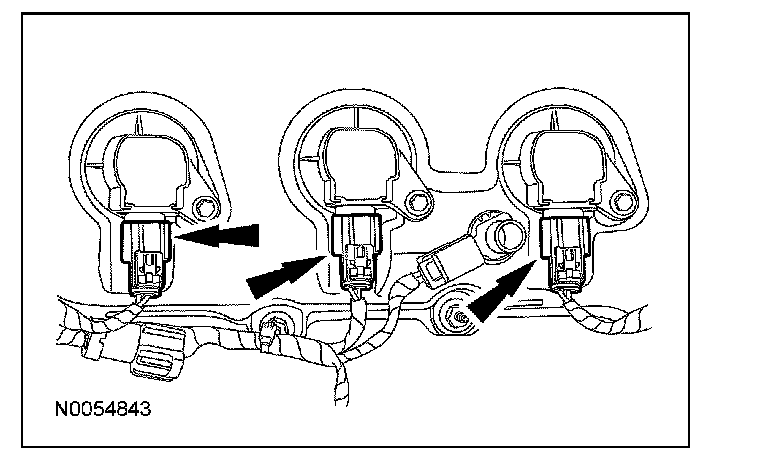
78. Disconnect the 3 RH coil-on-plug electrical connectors.
79. Detach all of the wiring harness retainers from the RH valve cover and stud bolts.
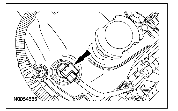
80. Disconnect the LH VCT solenoid electrical connector.
81. Disconnect the 3 LH coil-on-plug electrical connectors.
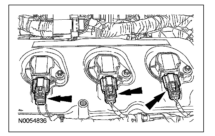
82. Detach all of the wiring harness retainers from the LH valve cover and stud bolts.
83. NOTE: LH shown, RH similar.
Remove the 6 bolts and the 6 coil-on-plugs.
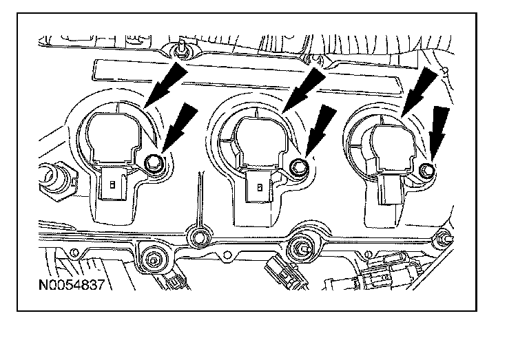
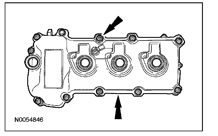
84. Remove the 11 stud bolts and the LH valve cover.
^ Discard the gasket.
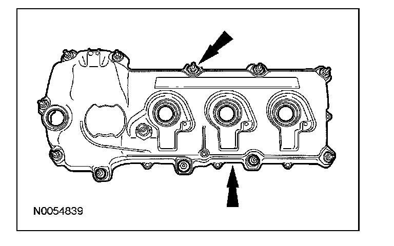
85. Remove the bolt, the 10 stud bolts and the RH valve cover.
^ Discard the gasket.
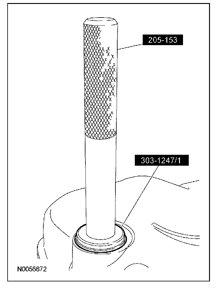
86. NOTE: VCT solenoid seal removal shown, spark plug tube seal removal similar.
Inspect the VCT solenoid seals and the spark plug tube seals. Install new seals if damaged.
^ Using the special tools, remove the seal(s).
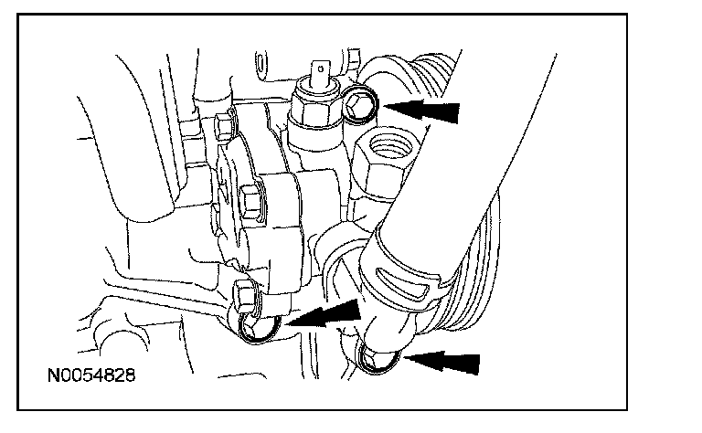
87. Remove the 3 bolts and the power steering pump.
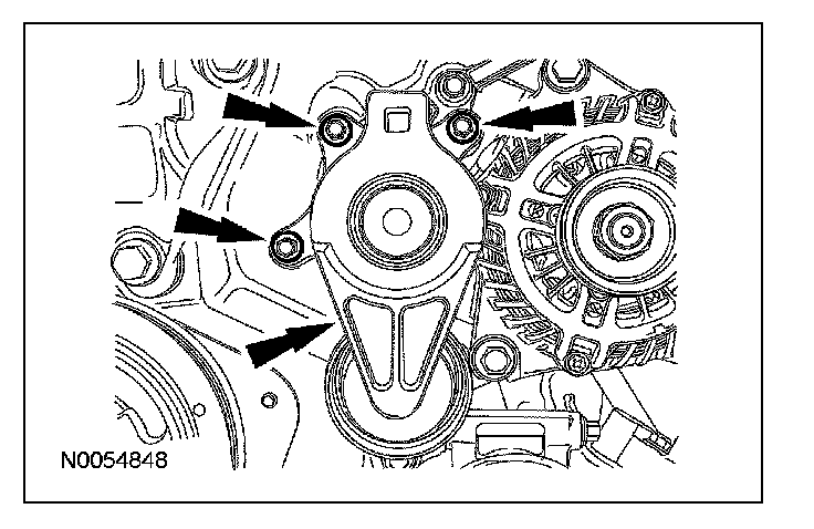
88. Remove the 3 bolts and the accessory drive belt tensioner.
89. Using the special tool, remove the crankshaft bolt and washer.
^ Discard the bolt.
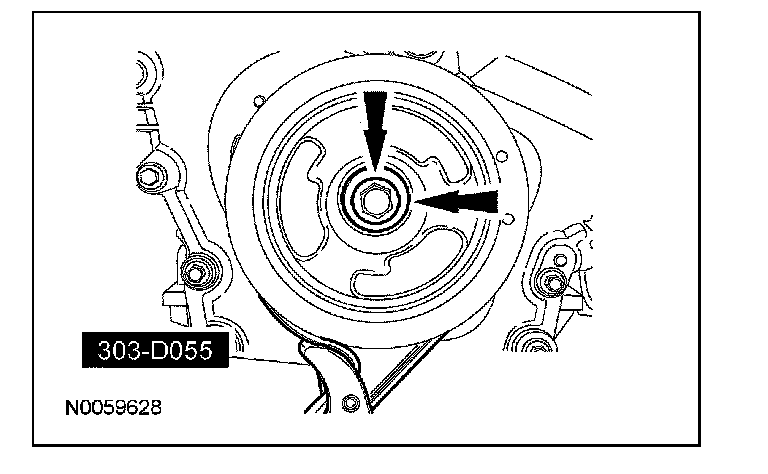
90. Using the special tool, remove the crankshaft pulley.
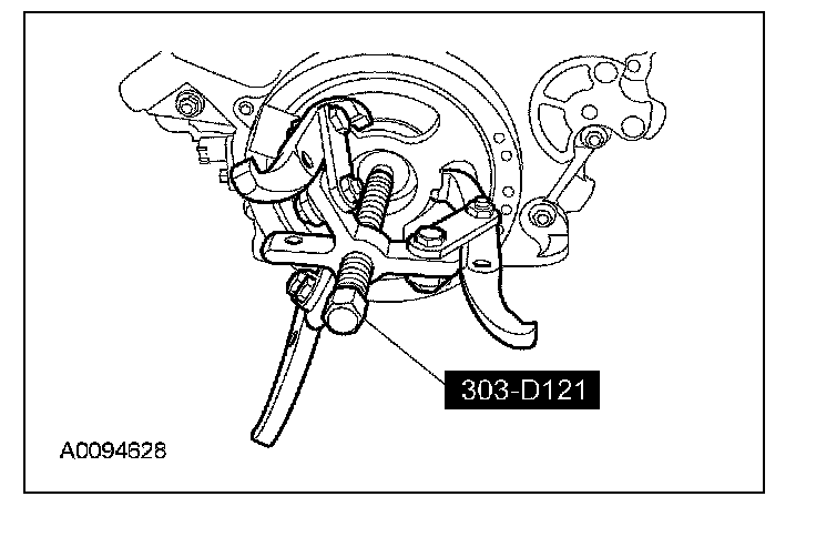
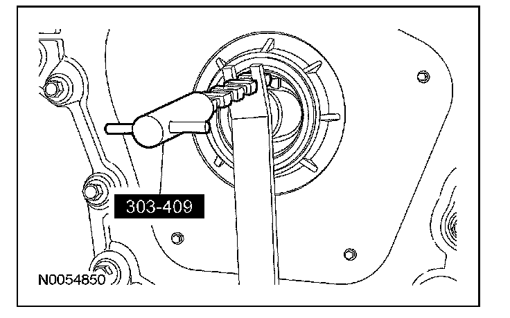
91. Using the special tool, remove and discard the crankshaft front seal.
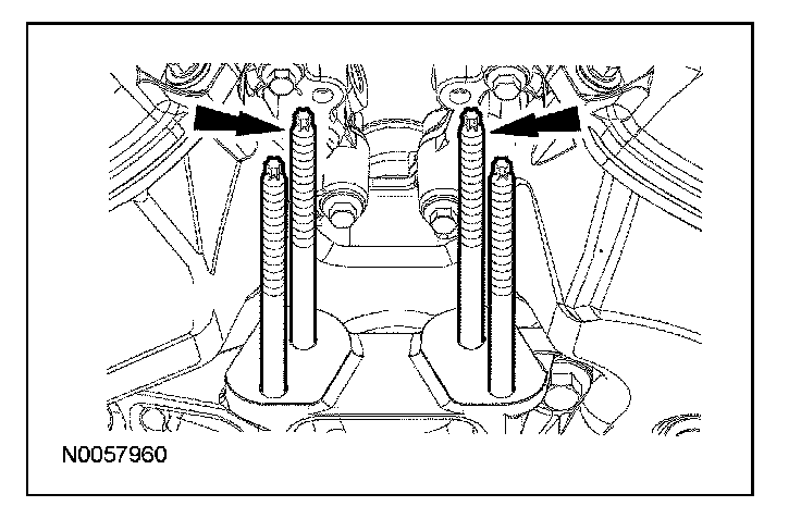
92. Remove the 2 bolts and the engine mount bracket.
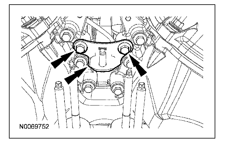
93. Remove the 2 engine mount studs.
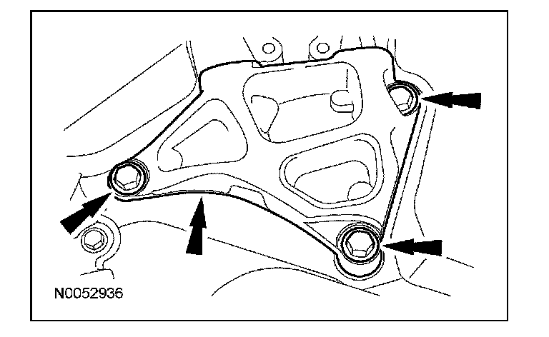
94. Remove the 3 bolts and the engine mount bracket.
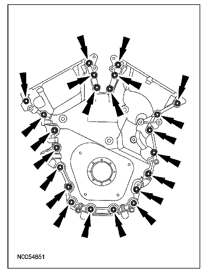
95. Remove the 22 engine front cover bolts.
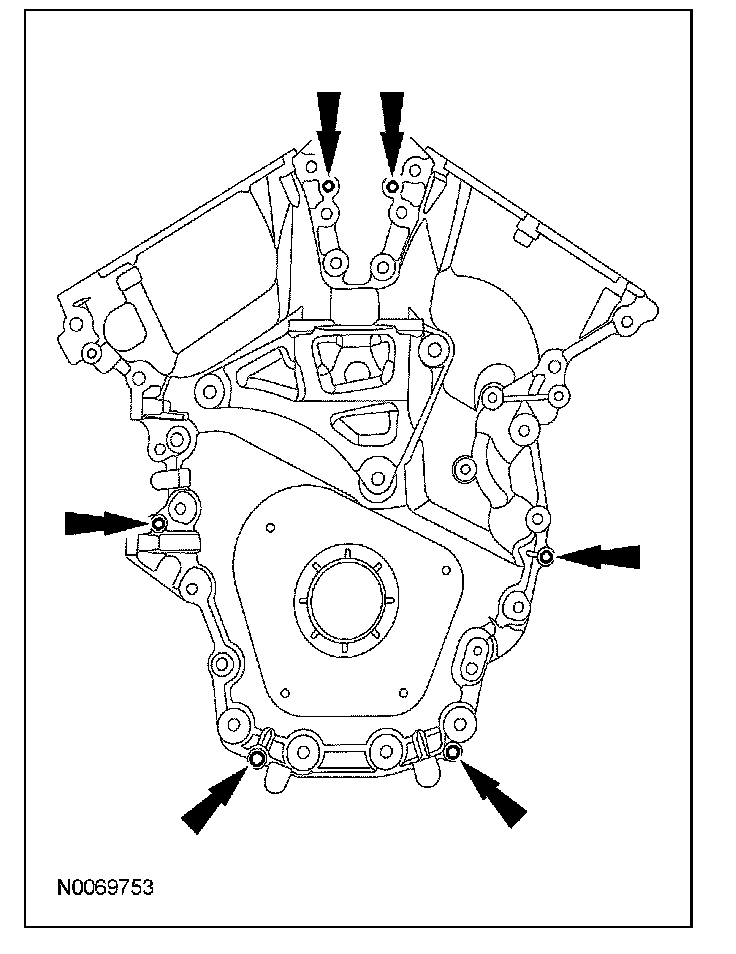
96. Install 6 of the engine front cover bolts (finger tight) into the 6 threaded holes in the engine front cover.
^ Tighten the bolts one turn at a time in a criss-cross pattern until the engine front cover-to-cylinder block seal is released.
^ Remove the engine front cover.
97. CAUTION: Only use a 3M Roloc(R) Bristle Disk (2-in white, part number 07528) to clean the engine front cover. Do not use metal scrapers, wire brushes or any other power abrasive disk to clean the engine front cover. These tools cause scratches and gouges that make leak paths.
Clean the engine front cover using a 3M Roloc(R) Bristle Disk (2-in white, part number 07528) in a suitable tool turning at the recommended speed of 15,000 rpm.
^ Thoroughly wash the engine front cover to remove any foreign material, including any abrasive particles created during the cleaning process.
98. CAUTION: Place clean, lint-free shop towels over exposed engine cavities. Carefully remove the towels so foreign material is not dropped into the engine. Any foreign material (including any material created while cleaning gasket surfaces) that enters the oil passages or the oil pan, may cause engine failure.
CAUTION: Do not use wire brushes, power abrasive discs or 3M Roloc(R) Bristle Disk (2-in white part number 07528) to clean the sealing surfaces. These tools cause scratches and gouges that make leak paths. They also cause contamination that will cause premature engine failure. Remove all traces of the gasket.
Clean the sealing surfaces of the cylinder block in the following sequence.
1 Remove any large deposits of silicone or gasket material.
2 Apply silicone gasket remover and allow to set for several minutes.
3 Remove the silicone gasket remover. A second application of silicone gasket remover may be required if residual traces of silicone or gasket material remain.
4 Apply metal surface prep to remove any remaining traces of oil or coolant and to prepare the surfaces to bond. Do not attempt to make the metal shiny. Some staining of the metal surfaces is normal.
5 Make sure the 2 locating dowel pins are seated correctly in the cylinder block.