Halfshaft - RH
Halfshaft - RHSpecial Tool(s):
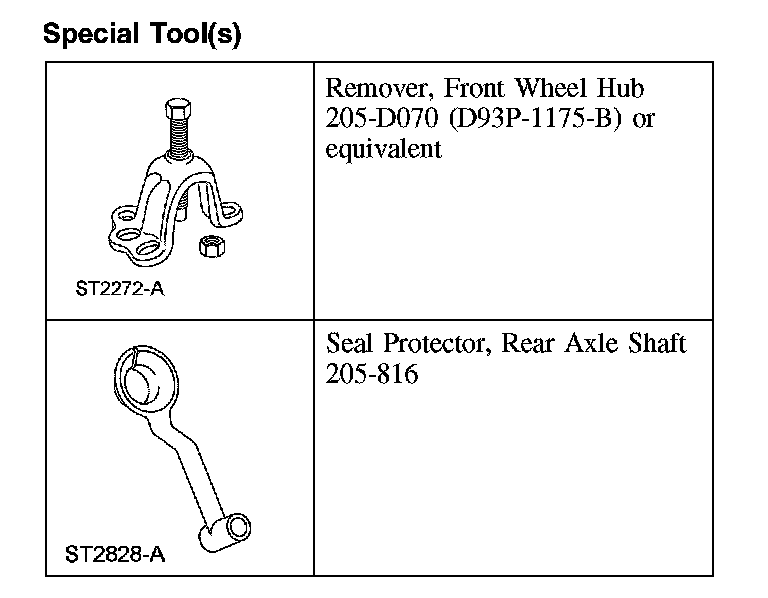
Removal
All vehicles
1. With the vehicle in NEUTRAL, position it on a hoist. For additional information, refer to Maintenance/Service and Repair.
2. Remove the front tire and wheel.
3. NOTE: Apply the brake to keep the halfshaft from rotating.
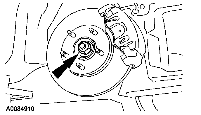
Remove and discard the front wheel hub nut.
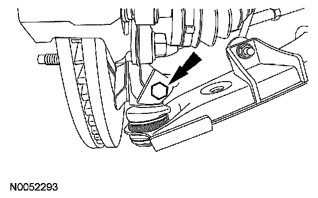
4. Remove the ball joint pinch bolt from the knuckle and separate the lower control arm.
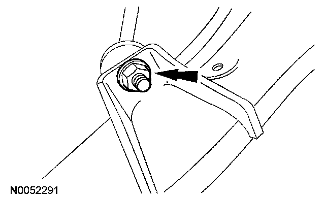
5. Remove the stabilizer bar link nut and position the link aside.
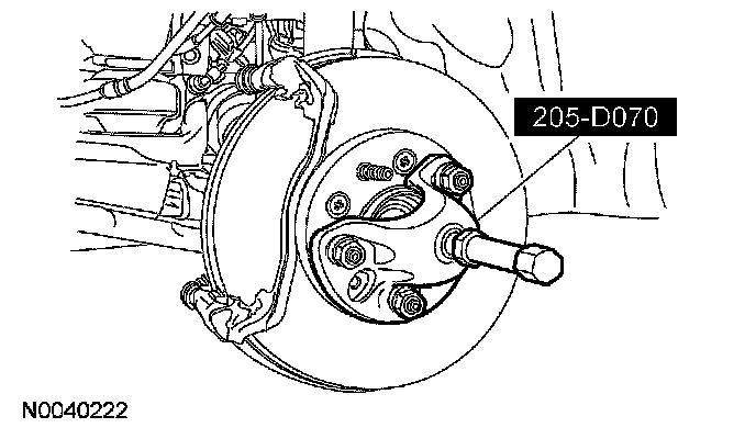
6. Using the special tool, separate the halfshaft from the wheel hub.
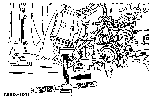
7. NOTE: Support the knuckle with a suitable jackstand.
Pull the knuckle outboard and rotate it toward the rear of the vehicle.
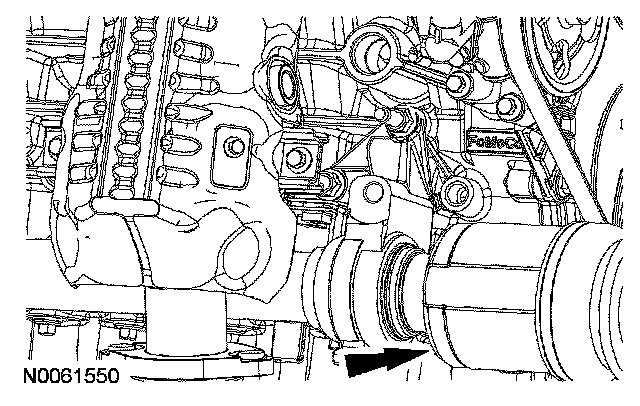
Front wheel drive (FWD) vehicles
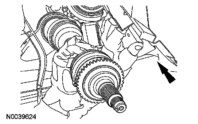
8. Use a brass drift to strike the right side halfshaft in the indicated area and separate the RH halfshaft from the intermediate shaft.
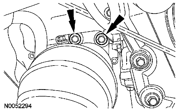
All wheel drive (AWD) vehicles
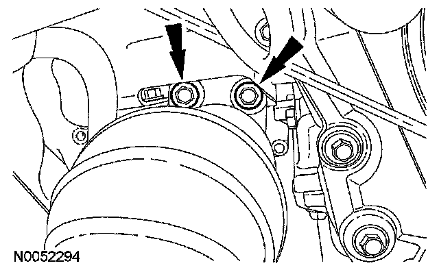
9. Remove the 2 bearing support bolts.
10. Remove the right halfshaft and intermediate shaft as an assembly.
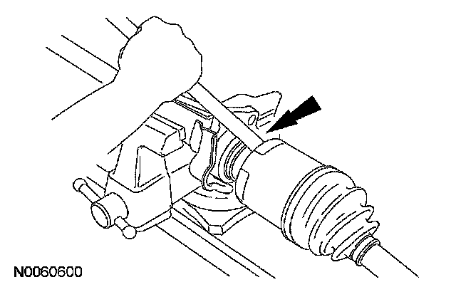
11. Place the intermediate shaft in a vise and disconnect the halfshaft from the intermediate shaft by striking the joint housing.
All vehicles
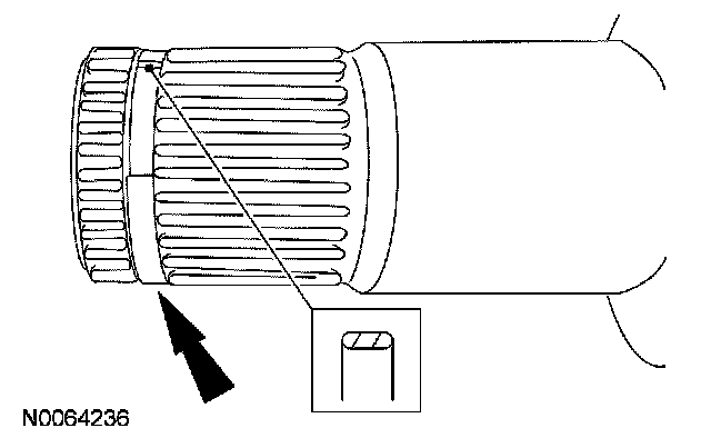
12. Remove and discard the circlip from the intermediate shaft.
Installation
All vehicles
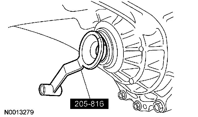
1. Position the special tool over the halfshaft oil seal.
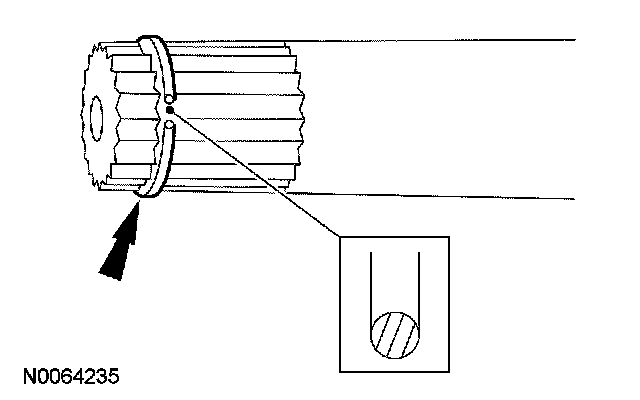
2. Install a new 30 mm (1.181 inch) intermediate shaft circlip.
AWD vehicles
3. NOTE: Pull the right side inboard joint outward to make sure the circlip is locked.
Align the splines on the right side shaft with the intermediate shaft and push the stub shaft in until the circlip locks the shafts together.
4. Position the assembly in the vehicle aligning the splines on the intermediate shaft with the transmission splines.
5. Install the 2 intermediate shaft support bearing bolts.
^ Tighten to 40 Nm (30 ft. lbs).
FWD vehicles
6. NOTE: Pull the right side inboard joint outward to make sure the circlip is locked.
Align the splines on the right side shaft with the intermediate shaft and push the stub shaft in until the circlip locks the shafts together.
All vehicles
7. Insert the halfshaft into the wheel hub.
8. Rotate the knuckle into position.
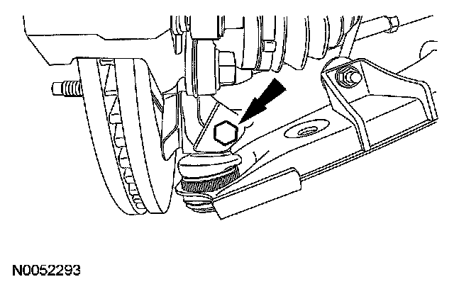
9. Install the ball joint in the knuckle and install the pinch bolt.
^ Tighten to 115 Nm (85 ft. lbs).
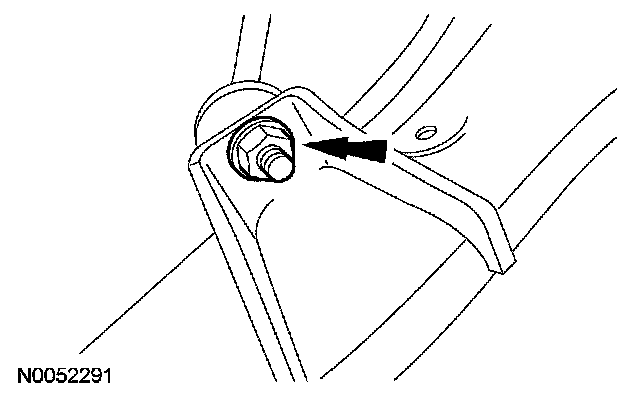
10. Position the stabilizer bar link and install the link nut.
^ Tighten to 55 Nm (41 ft. lbs).
11. Using a suitable tool, install the halfshaft in the wheel hub.
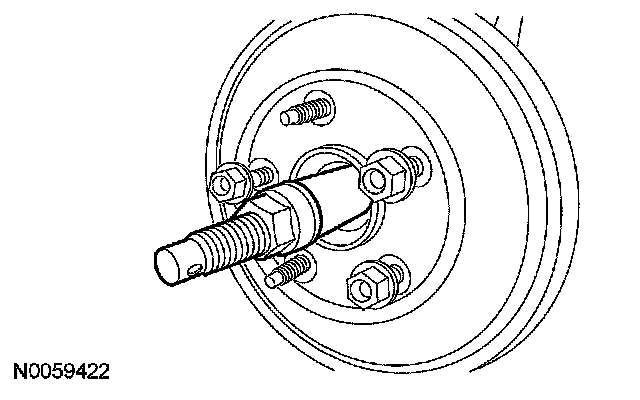
12. CAUTION: Do not tighten the front wheel hub nut with the vehicle on the ground. The nut must be tightened to specification before the vehicle is lowered onto the wheels. Wheel bearing damage will occur if the wheel bearing is loaded with the weight of the vehicle applied.
NOTE: Apply the brake to keep the halfshaft from rotating.
Install a new front wheel hub nut.
^ Tighten to 350 Nm (258 ft. lbs).
13. Install the front tire and wheel.