Part 2
CamshaftRemoval (Steps 41-80)
41. Remove the 2 nuts and the roll restrictor heat shield.
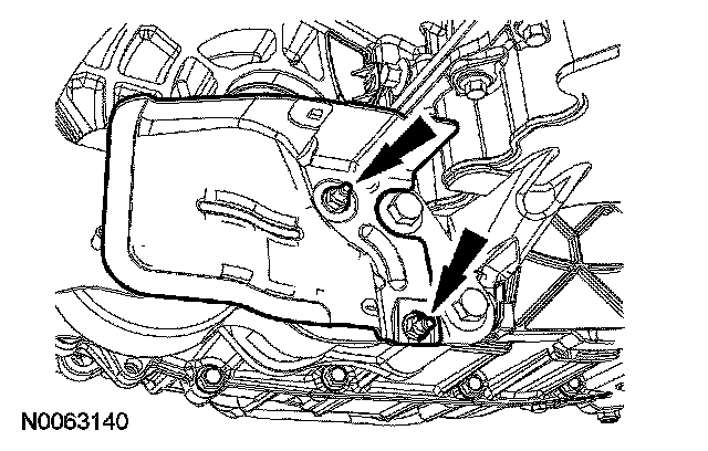
42. Remove the engine roll restrictor-to-subframe through bolt.
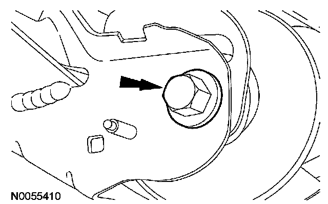
43. Remove and discard the power steering pressure (PSP) tube-to-pump banjo bolt and the 2 seals.
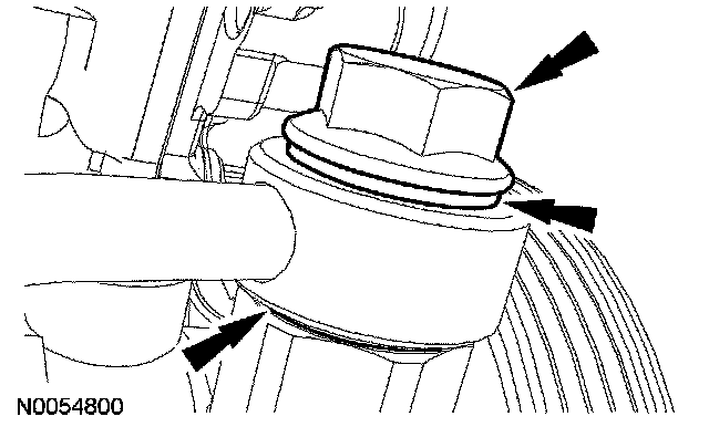
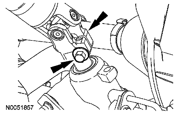
44. CAUTION: Do not allow the intermediate shaft to rotate while it is disconnected from the gear or damage to the clockspring can occur. If there is evidence that the intermediate shaft has rotated, the clockspring must be removed and recentered. For additional information, refer to Air Bag Systems.
Remove and discard the steering intermediate shaft bolt.
^ Separate the steering intermediate shaft from the steering gear.
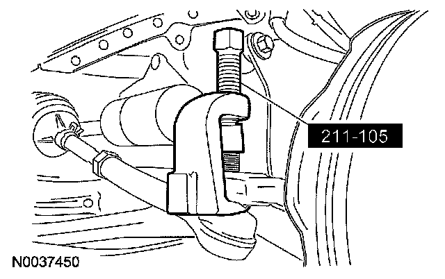
45. NOTE: RH shown, LH similar.
Remove and discard the cotter pins and tie-rod end nuts.
^ Using the special tool, separate the tie-rod ends from the wheel knuckles.
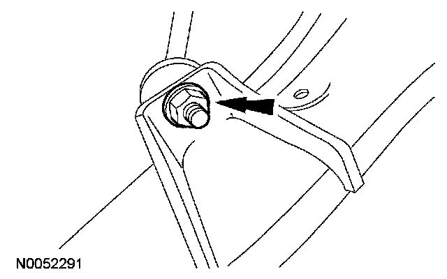
46. NOTE: RH shown, LH similar.
Remove the 2 stabilizer link-to-lower control arm nuts and separate the stabilizer bar links from the lower control arms.
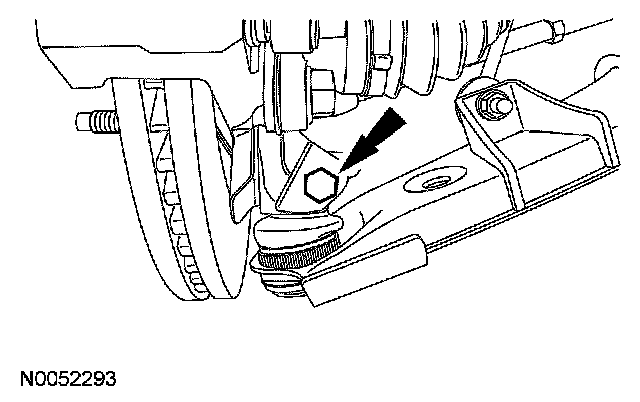
47. NOTE: RH shown, LH similar.
Remove the lower control arm-to-knuckle pinch bolts and separate the lower control arms from the knuckles.
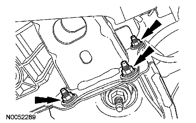
48. Remove the 3 RH subframe-to-lower bumper nuts.
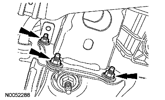
49. Remove the 3 LH subframe-to-lower bumper nuts and separate the lower bumper from the subframe.
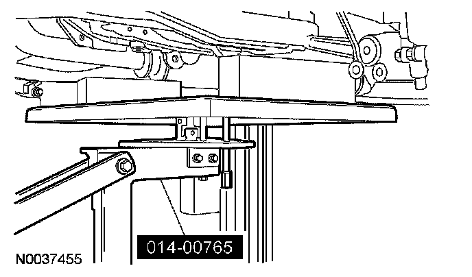
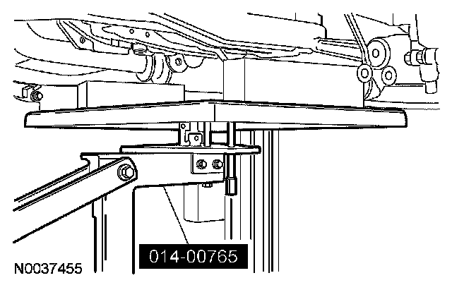
50. Position the special tool under the subframe assembly.
51. Remove the 2 nuts, 4 bolts and the subframe support brackets.
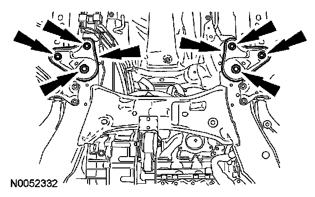
52. Remove the 2 front subframe nuts.
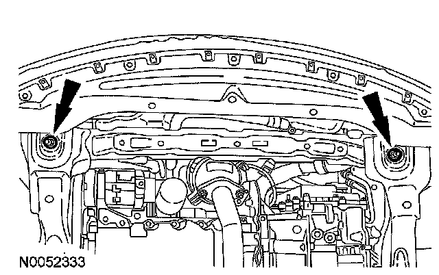
53. Remove the 2 middle subframe nuts.
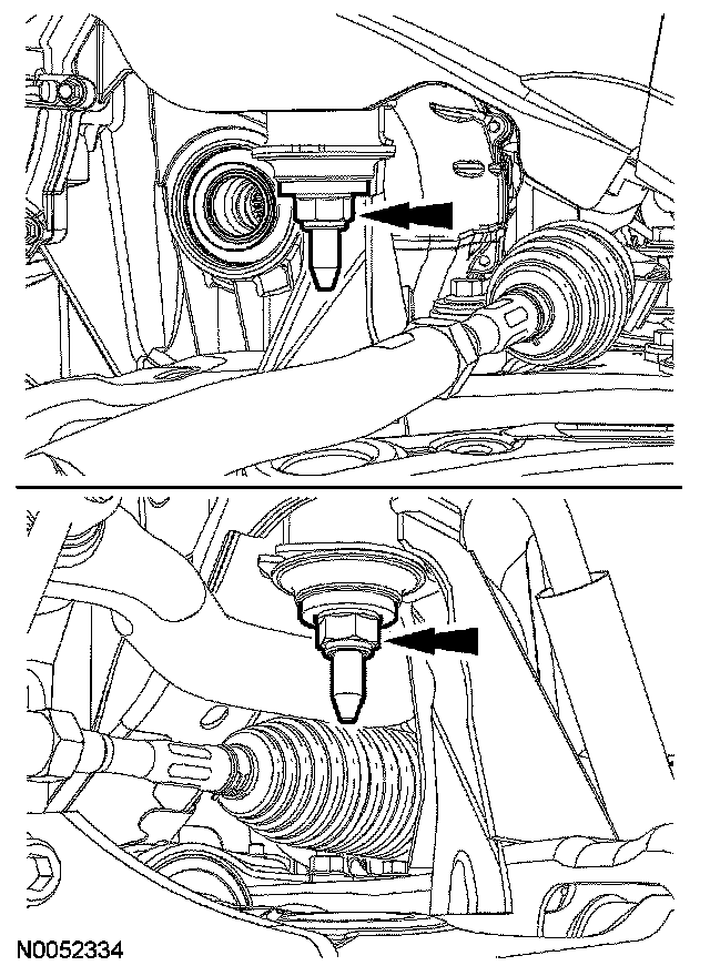
54. Using the special tool, lower the subframe assembly from the vehicle.
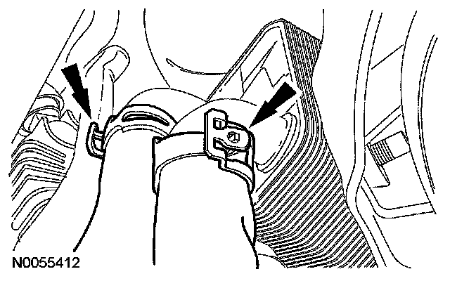
55. If equipped, disconnect the oil cooler coolant hoses.
56. Using the special tools, separate the LH halfshaft from the transaxle and support the halfshaft with a length of mechanic's wire.
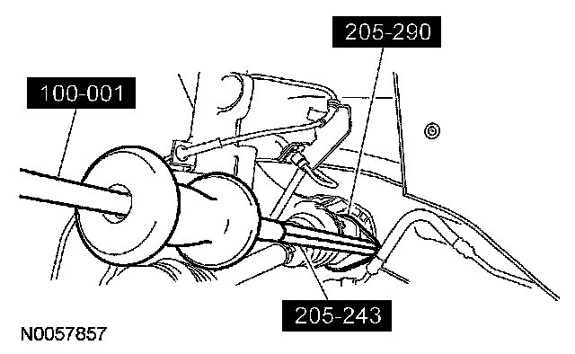
57. Using the special tool, separate the RH halfshaft from the hub.
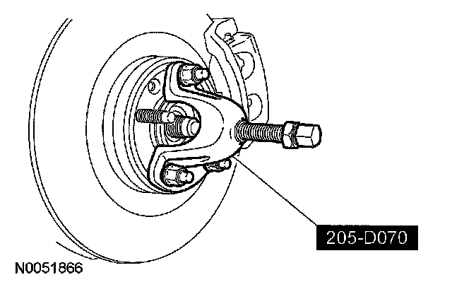
Front wheel drive (FWD) vehicles
58. Remove the 2 RH catalytic converter support bracket bolts.
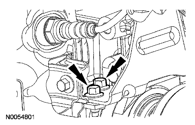
59. Remove the bolt, the nut and the RH catalytic converter support bracket.
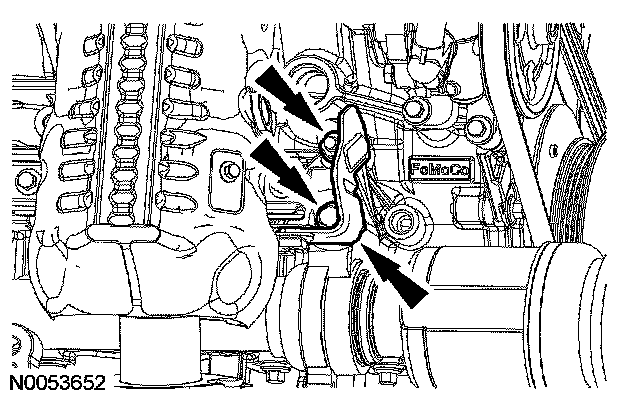
60. Remove the 2 stud bolts and the RH halfshaft/intermediate shaft assembly.
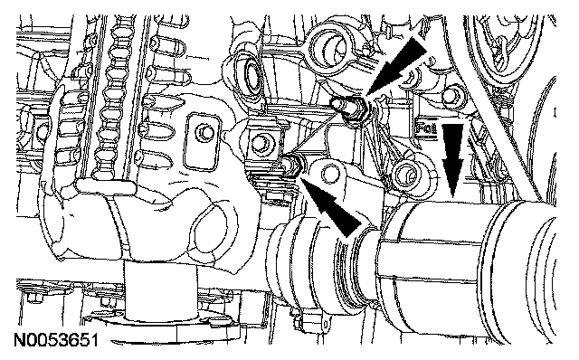
AWD vehicles
61. Remove the 2 RH halfshaft bearing support bracket bolts and the RH halfshaft/intermediate shaft assembly.
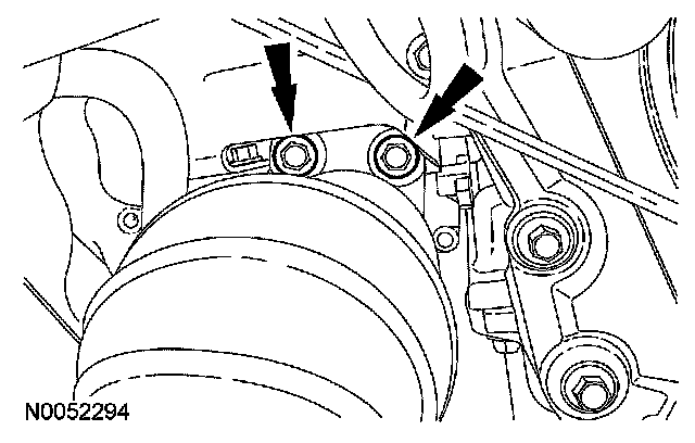
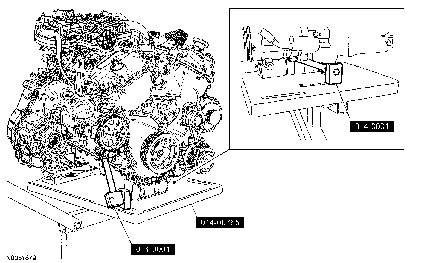
All vehicles
62. NOTE: Position a block of wood under the transaxle.
Install the special tools.
63. Remove the transaxle support insulator through bolt and nut.
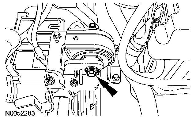
64. Remove the 3 nuts, the bolt and the transaxle support insulator bracket.
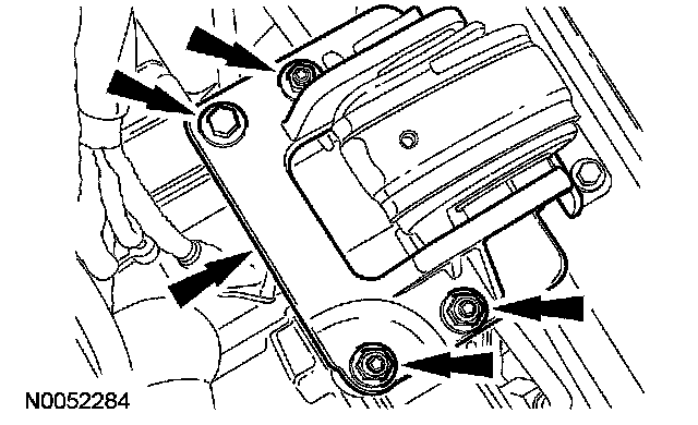
65. Remove the nut, bolt and engine mount brace.
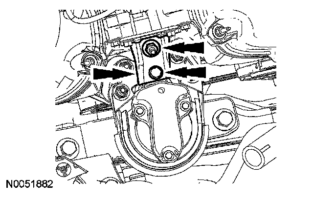
66. Remove the 4 engine mount nuts.
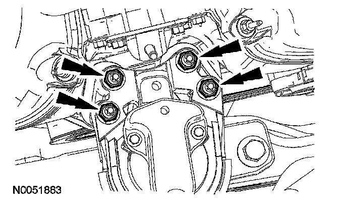
67. Remove the 3 bolts and the engine mount.
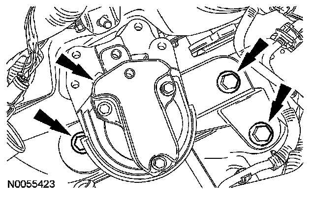
68. Lower the engine and transaxle assembly from the vehicle.
69. If equipped, detach the engine block heater wiring harness retainers and position the harness aside.
70. Disconnect the positive crankcase ventilation (PCV) fitting electrical connector.
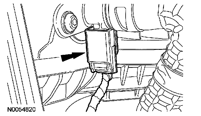
71. Disconnect the PCV hose from the PCV valve.
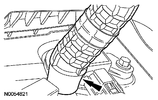
72. Disconnect the throttle body electrical connector.
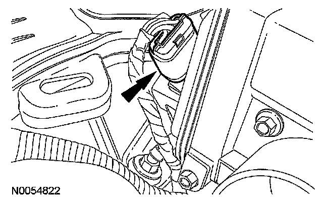
73. Detach the wiring harness retainers from the upper intake manifold.
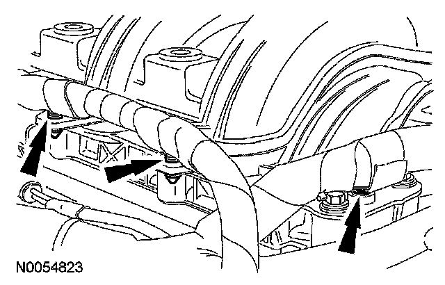
74. Remove the upper intake manifold support bracket bolt.
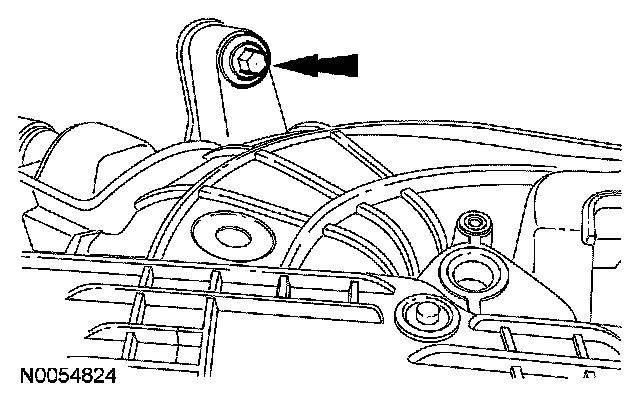
75. Remove the upper intake manifold support bracket bolt.
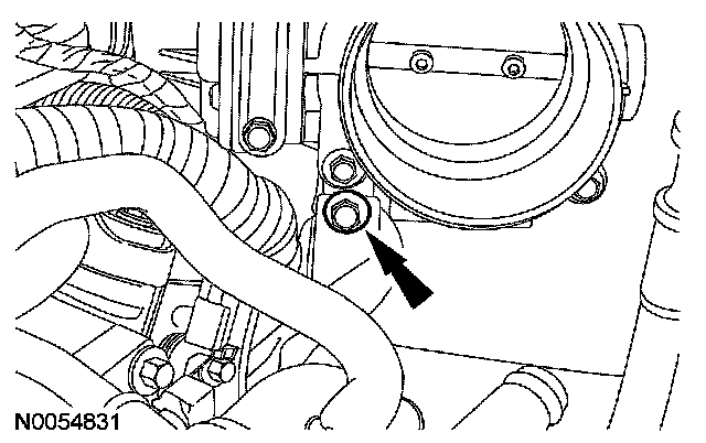
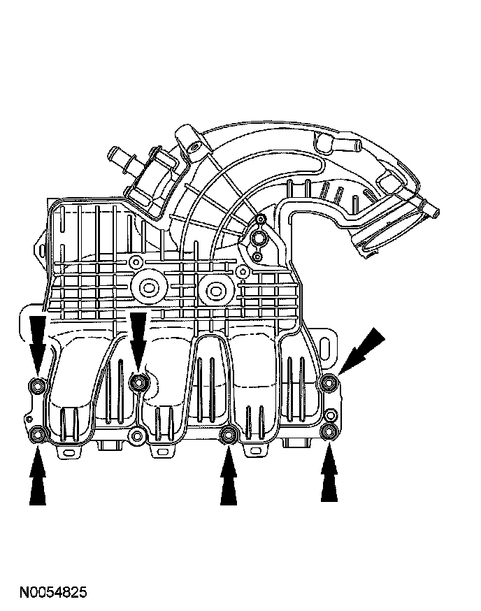
76. Remove the 6 bolts and the upper intake manifold.
^ Discard the gaskets.
77. Disconnect the RH catalyst monitor electrical connector.
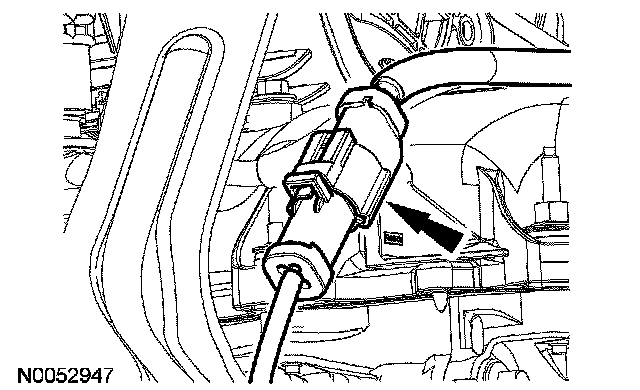
78. Disconnect the PSP switch electrical connector.
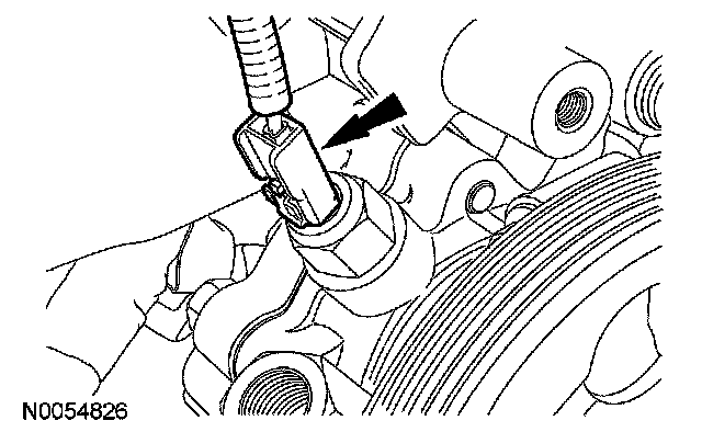
79. Disconnect the RH variable camshaft timing (VCT) solenoid electrical connector.
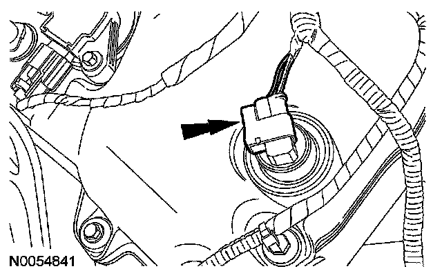
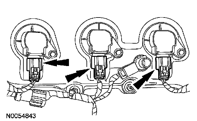
80. Disconnect the 3 RH coil-on-plug electrical connectors.