Pinpoint Test I: The Defrost System Will Not Shut Off Automatically
- I1 CHECK FOR A SHORT TO POWER
- Key in OFF position.
- Disconnect: Heated Rear Window Relay.
- Key in START position.
- With the engine running, measure the voltage between the heated rear window relay C2021 pin 87, CJB side and ground.
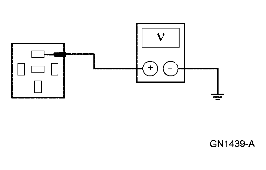 Courtesy of FORD MOTOR CO.
- Is any voltage present?
- Yes
: Go to I2.
- No
: Go to I4.
- I2 CHECK CIRCUIT 15S-HB19 (GN/BU)
- Key in OFF position.
- Disconnect: CJB C270a.
- Key in START position.
- With the engine running, measure the voltage between the heated rear window relay C2021 pin 87, CJB side and ground.
Courtesy of FORD MOTOR CO.
- Is the voltage greater than 10 volts?
- Yes
: Go to I3.
- No
: REPAIR the circuit. TEST the system for normal operation.
- I3 CHECK CIRCUIT 15S-HB2 (GN/BU)
- Key in OFF position.
- Disconnect: CJB C270d.
- Key in START position.
- With the CJB C270a still disconnected and the engine running, measure the voltage between the heated rear window relay C2021 pin 87, CJB side and ground.
Courtesy of FORD MOTOR CO.
- Is the voltage greater than 10 volts?
- Yes
: INSTALL a new CJB. TEST the system for normal operation.
- No
: REPAIR the circuit. TEST the system for normal operation.
- I4 CHECK THE HEATED REAR WINDOW RELAY COIL GROUND CIRCUIT
- Key in OFF position.
- Disconnect: Heater Control Module C2263.
- Key in START position.
- With the engine running, measure the resistance between the heated rear window relay C2021 pin 85, CJB side and ground.
 Courtesy of FORD MOTOR CO.
- Is the resistance greater than 10,000 ohms?
- Yes
: Go to I5.
- No
: Go to I6.
- I5 CHECK THE HEATER CONTROL MODULE OPERATION
- Disconnect all heater control module connectors.
- Check for:
- Corrosion
- Pushed-out pins
- Connect all heater control module connectors and make sure they seat correctly.
- Operate the system and verify the concern is still present.
- Is the concern still present?
- Yes
: INSTALL a new heater control module. Refer to CONTROL COMPONENTS
. TEST the system for normal operation.
- No
: The system is working correctly at this time. The concern may have been caused by a loose or corroded connector. CLEAR the DTCs. REPEAT the self-test.
- I6 CHECK THE GENERIC ELECTRONIC MODULE (GEM) INTEGRITY
- Key in OFF position.
- Disconnect: GEM C201e.
- Measure the resistance between the heated rear window relay C2021 pin 85, CJB side and ground.
Courtesy of FORD MOTOR CO.
- Is the resistance greater than 10,000 ohms?
- Yes
: Go to I7.
- No
: REPAIR the circuit. CLEAR the DTCs. REPEAT the self-test.
- I7 CHECK FOR CORRECT GEM OPERATION
- Disconnect all GEM connectors.
- Check for:
- Corrosion
- Pushed-out pins
- Connect all GEM connectors and make sure they seat correctly.
- Operate the system and verify the concern is still present.
- Is the concern still present?
- Yes
: INSTALL a new GEM. Refer to MULTIFUNCTION ELECTRONIC MODULES
. TEST the system for normal operation.
- No
: The system is operating correctly at this time. The concern may have caused by a loose or corroded connector. CLEAR the DTCs. REPEAT the self-test.