Pinpoint Test C: The High Beams Are Inoperative
- C1 CHECK THE FLASH-TO-PASS FEATURE
- Key in ON position.
- Operate the flash-to-pass feature.
- Does the flash-to-pass feature operate correctly?
- C2 CHECK CIRCUIT 30-LE13 (RD) FOR VOLTAGE
- Key in OFF position.
- Disconnect: High Beam Relay C1050.
- Measure the voltage between the high beam relay C1050-3, circuit 30-LE13 (RD), harness side and ground.
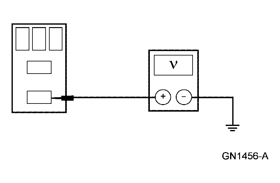 Courtesy of FORD MOTOR CO.
- Is the voltage greater than 10 volts?
- Yes
: GO to C3.
- No
: REPAIR or INSTALL a new BJB. TEST the system for normal operation.
- C3 CHECK CIRCUIT 91-LE12 (BK/YE) FOR AN OPEN
- Measure the resistance between the high beam relay C1050-2, circuit 91-LE12 (BK/YE), harness side and ground.
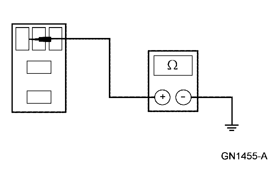 Courtesy of FORD MOTOR CO.
- Is the resistance less than 5 ohms?
- Yes
: GO to C4.
- No
: REPAIR or INSTALL a new BJB. TEST the system for normal operation.
- C4 CHECK CIRCUIT 15S-LE12 (GN/YE) FOR VOLTAGE
- Key in ON position.
- Place the headlamp switch in the headlamps ON position.
- Place the multifunction switch in the high beam position.
- Measure the voltage between the high beam relay C1050-1, circuit 15S-LE12 (GN/YE), harness side and ground.
 Courtesy of FORD MOTOR CO.
- Is the voltage greater than 10 volts?
- Yes
: INSTALL a new high beam relay. TEST the system for normal operation.
- No
: GO to C5.
- C5 CHECK THE MULTIFUNCTION SWITCH
- Carry out the multifunction switch component test. Refer to COMPONENT TESTING
article
.
- Is the multifunction switch OK?
- Yes
: REPAIR circuit 15S-LE12 (GN/YE). TEST the system for normal operation.
- No
: INSTALL a new multifunction switch. REFER to STEERING COLUMN SWITCHES
. TEST the system for normal operation.