Pinpoint Test A: The Daytime Running Lamps (DRL) Are Inoperative
- A1 CHECK THE LOW BEAM HEADLAMPS
- Key in ON position.
- Make sure the multifunction switch is not in the high beam position.
- Switch the headlamps on.
- Check the low beams.
- Do the low beams illuminate with full intensity?
- A2 CHECK THE POWER SUPPLY TO THE DRL RELAY
- Switch the headlamps off.
- Key in OFF position.
- Disconnect: DRL Relay C1000.
- Measure voltage between the DRL relay C1000 pin 3, harness side and ground.
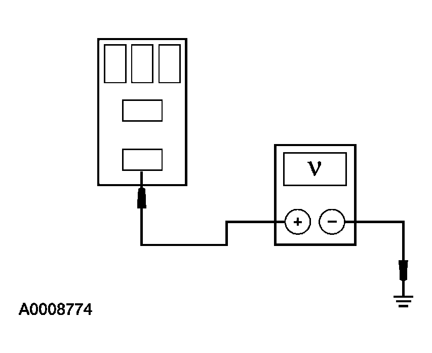 Courtesy of FORD MOTOR CO.
- Is voltage greater than 10 volts?
- Yes
: GO to A3.
- No
: REPAIR or INSTALL a new BJB. TEST the system for normal operation.
- A3 CHECK THE DRL RELAY
- Carry out the DRL Relay component test. Refer to COMPONENT TESTING
.
- Is the relay OK?
- Yes
: GO to A4.
- No
: INSTALL a new DRL relay. TEST the system for normal operation.
- A4 CHECK THE DRL RESISTOR WIRE
- Connect a fused (20A) jumper wire between the DRL relay C1000 pin 3, harness side and the DRL relay C1000 pin 5, circuit 15S-LE8 (GN/RD), harness side.
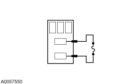 Courtesy of FORD MOTOR CO.
- Do the headlamps illuminate?
- Yes
: REMOVE the jumper wire. GO to A6.
- No
: REMOVE the jumper wire. GO to A5.
- A5 CHECK THE LOW BEAM RELAY
- Disconnect: Low Beam Relay C1049.
- Carry out the Low Beam Relay component test. Refer to COMPONENT TESTING
.
- Is the relay OK?
- Yes
: REPAIR the DRL resistor wire, circuit 15S-LE8 (GN/RD). TEST the system for normal operation.
- No
: INSTALL a new low beam relay. TEST the system for normal operation.
- A6 CHECK CIRCUIT 91-LE6 (BK/RD) FOR AN OPEN
- Measure the resistance between the DRL relay C1000 pin 2, circuit 91-LE6 (BK/RD), harness side and ground.
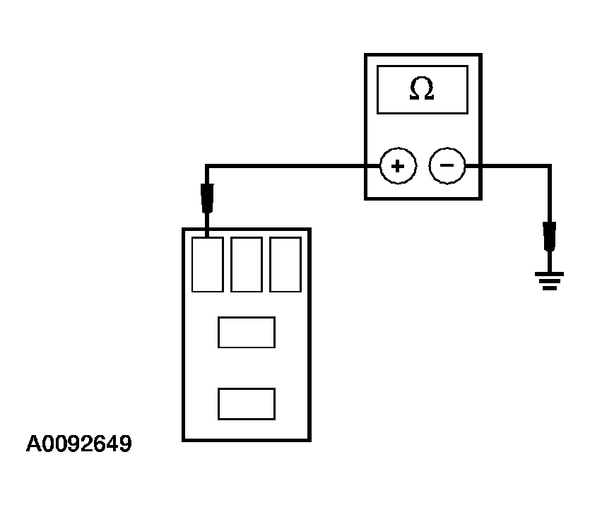 Courtesy of FORD MOTOR CO.
- Is the resistance less than 5 ohms?
- Yes
: GO to A7.
- No
: REPAIR the circuit. TEST the system for normal operation.
- A7 CHECK CIRCUIT 15S-LE6 (GN/YE) FOR AN OPEN
- Key in ON position.
- Disconnect: Headlamp Switch C205.
- Connect a fused jumper wire between the headlamp switch C205 pin 8, circuit 15-LE29 (GN/BK), harness side and the headlamp switch C205 pin 4, circuit 15S-LE6 (GN/YE), harness side.
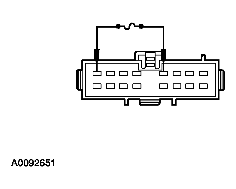 Courtesy of FORD MOTOR CO.
- Do the headlamps illuminate with reduced intensity?
- Yes
: INSTALL a new headlamp switch. REFER to EXTERIOR LIGHTING
. TEST the system for normal operation.
- No
: REPAIR the circuit. TEST the system for normal operation.