Pinpoint Test A: No Communication With The Instrument Cluster
- A1 CHECK CIRCUIT 29-GG14 (OG) FOR POWER
- Key in OFF position.
- Disconnect: Instrument Cluster C2220.
- Measure the voltage between the instrument cluster C2220 pin 28, circuit 29-GG14 (OG), harness side and ground.
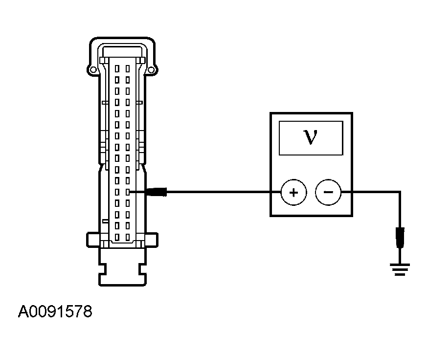 Courtesy of FORD MOTOR CO.
- Is the voltage greater than 10 volts?
- Yes
: GO to A2.
- No
: REPAIR the circuit. TEST the system for normal operation.
- A2 CHECK CIRCUIT 75-GG14 (YE/BU) FOR POWER
- Key in ACCESSORY position.
- Measure the voltage between the instrument cluster C2220 pin 6, circuit 75-GG14 (YE/BU), harness side and ground.
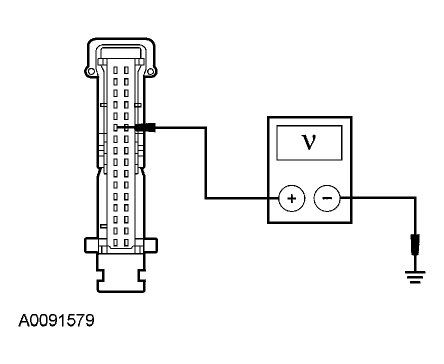 Courtesy of FORD MOTOR CO.
- Is the voltage greater than 10 volts?
- Yes
: GO to A3.
- No
: REPAIR the circuit. TEST the system for normal operation.
- A3 CHECK CIRCUIT 15-GG14 (GN/RD) FOR POWER
- Key in ON position.
- Measure the voltage between the instrument cluster C2220 pin 12, circuit 15-GG14 (GN/RD), harness side and ground.
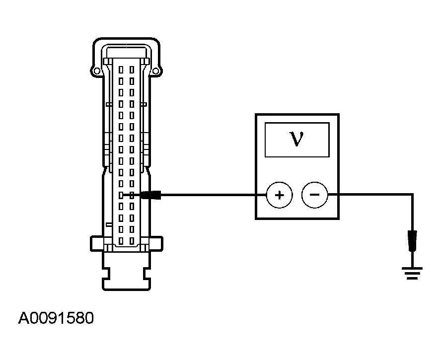 Courtesy of FORD MOTOR CO.
- Is the voltage greater than 10 volts?
- Yes
: GO to A4.
- No
: REPAIR the circuit. TEST the system for normal operation
- A4 CHECK CIRCUIT 91-GG14 (BK/OG) FOR AN OPEN
- Key in OFF position.
- Measure the resistance between the instrument cluster C2220 pin 30, circuit 91-GG14 (BK/OG), harness side and ground.
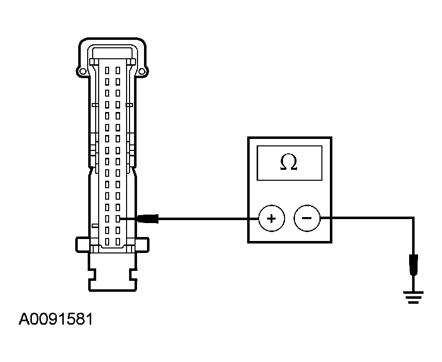 Courtesy of FORD MOTOR CO.
- Is the resistance less than 5 ohms?
- Yes
: REFER to MODULE COMMUNICATIONS NETWORK
to continue diagnosis of the communications network.
- No
: REPAIR the circuit. TEST the system for normal operation.